


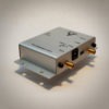
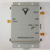
RF Signal Generator With Power Detector
The SynthNV is a CE certified, 34.4MHz to 4.4GHz software tunable RF signal generator controlled and powered by a PC running Windows 7 SP1 through Windows 10, or Android via itsUSB port. WinXP supported by older versions of SynthNV software. It includes an onboard RF power detector which can be used with the sweep function as a basic RF network analyzer.
The SynthNV also has nonvolatile onboard memory so it can be programmed to fire up by itself on any frequency, power, or modulation setting. This makes for a highly mobile, low power, and lightweight solution for your RF signal generation needs.
![]()
Powerful Features
Scalar Network Analyzer Functionality
Use this device as a generic RF signal generator in your test setup, or use it as a high quality local oscillator in your RF or microwave communication system. Simultaneously measure and graph RF power in real-time.
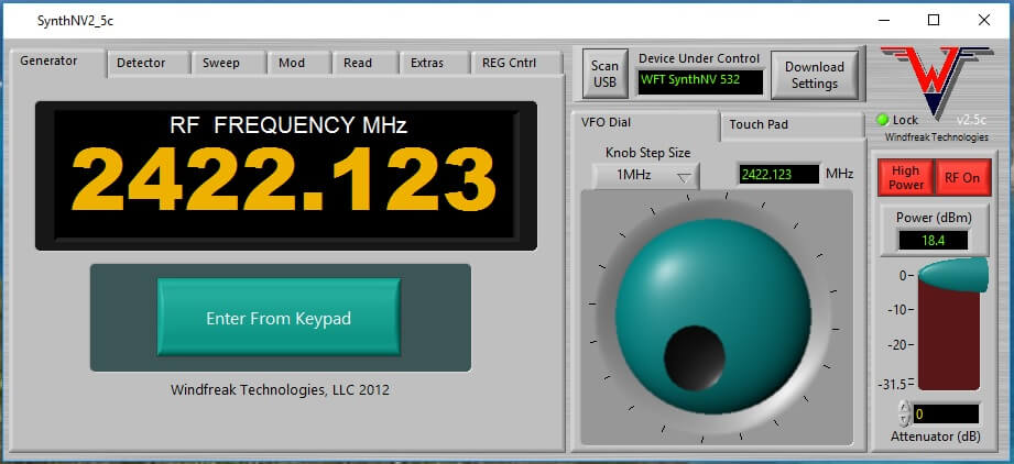
Shown below, the software is eloquently engineered giving professional performance at fractions the cost of a bench top generator.
You may enter data either with the touch pad, knob, directly with the PC keyboard, and also by clicking on arrows next to the controls.
RF Single Frequency Generation Tab
RF Sweep Generation Tab
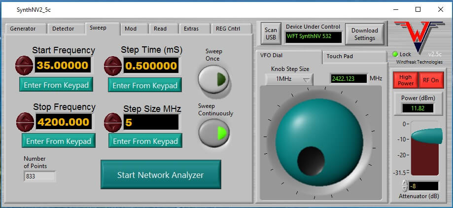
Settings Step as fast a 300uS per point. Resolution as low as 1KHz per step.
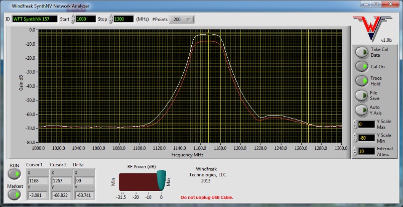
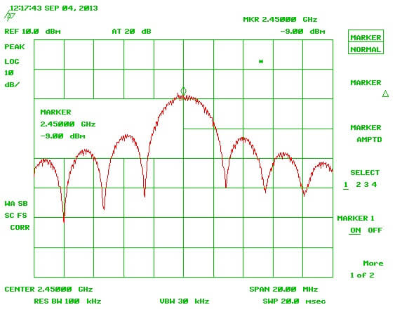
RF network analyzer application started from the Sweep Tab. Shown is an actual sweep from a 1167MHz bandpass filter. Expand the app to full screen, calibrate, use trace hold, and markers to measure your circuit performance easily. Below is a throughput measurement. Scroll down for a reflection measurement via Return Loss / VSWR Application Note.
Note: The SynthNV tends to work well with bandpass and lowpass filters but may have errors introduced by the harmonics when measuring highpass elements.
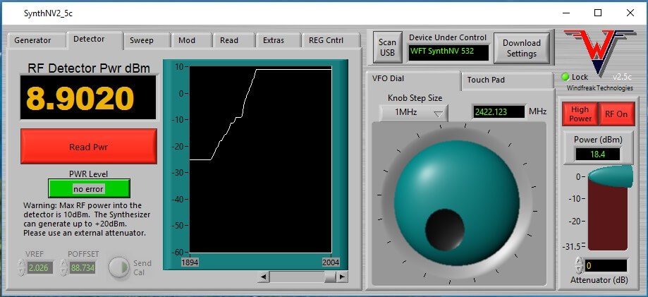
RF power measurement tab. (Continuously measure broadband RF power at Jll [10].)
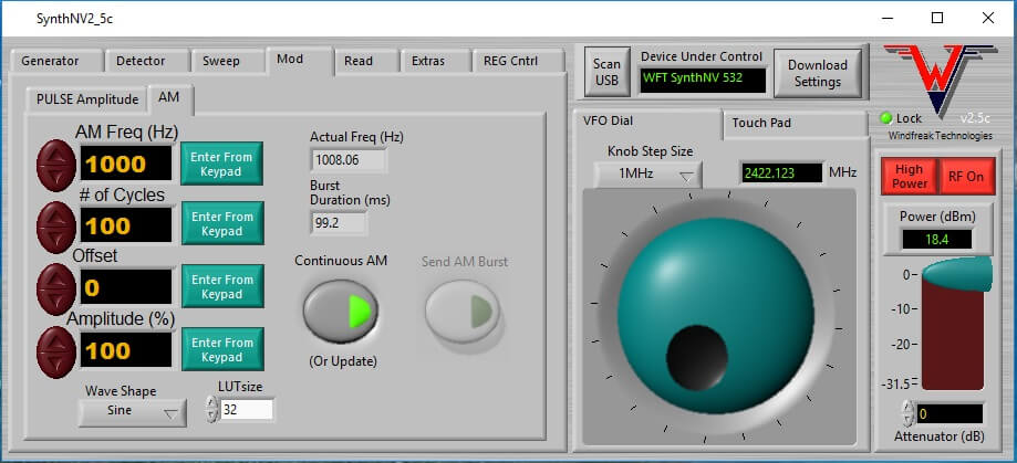
RF Amplitude Modulation tab. (Send burst or continuous AM with modulation rates up to 5KHz. Set the AM waveform between sinusoid, saw, or ramp. Software writers can even program arbitrary AM waveforms.)
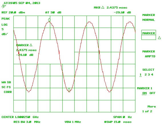
Shown is maximum deviation AM in 0 Hz mode on the spectrum analyzer (time domain).
RF Pulse Amplitude Modulation tab. (Send burst or continuous pulses with a resolution of 1uS steps.)
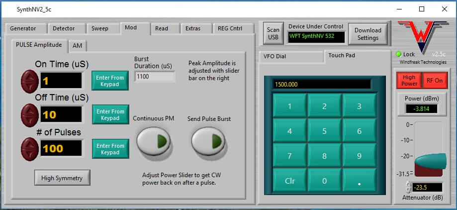
Shown (in the frequency domain) is the absolute shortest pulse of 400nS.
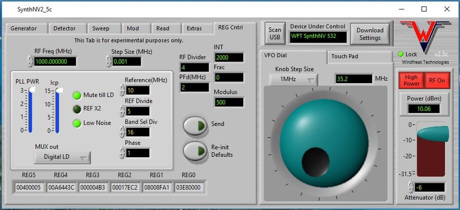
PLL Control tab. (Control some finer details of the ADF4351 to get higher accuracy or quality for a particular frequency.)
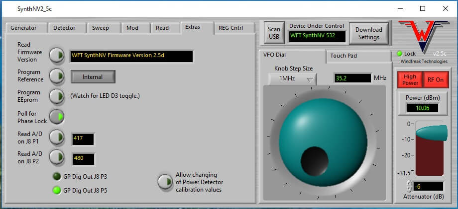
Extras tab. (Check SynthNV firmware version, set Internal or External Reference, save to SynthNV internal EEPROM memory Frequency, Power, Reference, Modulation and Sweep setup for standalone operation. Also write to the general purpose digital header pins on the SynthNV, or read analog signals from header pins.)
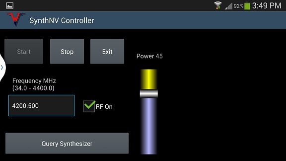
Android Controller. (Shown on a Galaxy S4. This program is BETA and supplied on request after purchase.)
Easy to Use Software
The software is easy to install and use. It can control multiple devices based on programmed serial numbers, do an RF CW frequency, run an RF sweep, perform basic scalar network analyzer functions, Amplitude Modulate and Pulse Modulate, save many settings to EEPROM, register real time power measurements on connector [10], and fine tune the PLL registers for experienced users. Control is very similar to a bench top signal generator. It is also touch panel friendly.
This software was written in Labview and the open source code is included so that you can modify and enhance any way you see fit for your own use. Please do not distribute. If you don’t own Labview, you will also get an executable that will install standalone and run on a PC. If you want to write your own software, it is best to get Labview and reverse engineer the Windfreak Labview source code. Labview is available with a free 1 month trial from National Instruments. All source code is sent on CD “saved as” using the latest version of Labview Basic. The device is easy to talk to via 1 simple command character followed program data. For example, setting frequency is done by sending “f1000.0” (without the quotes).
Please contact us if you want to develop software in Linux. We have a customer who wrote an API that works with the SynthNV and is sharing it for free.
**The SynthNV has been tested with a terminal program from the Google Play market called “Android USB Serial”. This program will let you send text commands to the SynthNV. The app is currently free. The only hardware it has been tested with to date is the Samsung Galaxy Note 1, Galaxy Tab 2, and Galaxy s4. To act as a USB host the phone needs a USB dongle which is about a $15 cable from Amazon. If you have success with your phone or tablet, please drop us an email so we can add it to the list of compatible hardware. We also have an app shown above that we will supply for free after you purchase the SynthNV. The SynthNV will also power off of the devices but no testing has been done on battery life or negative effects on the devices.
Both Pulse Modulation and Amplitude Modulation can happen in conjunction with a sweep. You can even program the SynthNV to do this without the PC when it powers up by itself.
Powerful Hardware
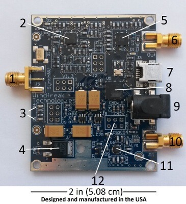
The technology is based on Analog Devices ADF4351 chip [2]. You can expect high quality RF performance at the RF connector [6] similar to the specs in the datasheet. The only significant RF difference from the ADF4351 datasheet is that the RF power is up to +19dBm settable in 1/2dB steps via the Hittite HMC625LP5 chip [5]. This chip is controlled via a high speed 6 bit parallel bus coming from the microcontroller chip [8].
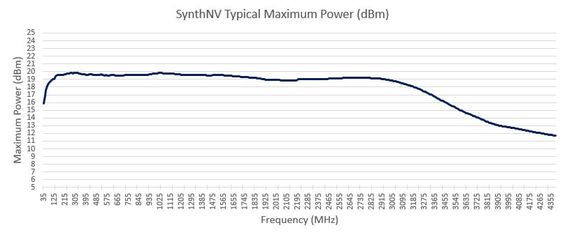
RF power (max) into a 50 ohm load is similar to the chart below.
Note: amplitude is adjustable via software over 2 amplitude ranges of 30dB in 1/2 dB steps for more than 60dB of adjustment.
Communications
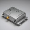
RF generator accuracy is based on an onboard 2.5ppm 10MHz crystal oscillator which is also routed to the outside world via the reference SMA connector [1]. This connector can also be used to input a higher precision reference if so desired.
The synthesizer will run off USB power. It will also run standalone via its DC power connector [9] and low dropout linear regulator [4]. The required voltage is a range from 6-9 volts DC at <300mA, with the center pin being positive and the outer conductor being ground. 12 volts is possible with enhanced heat sinking on the regulator.
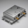
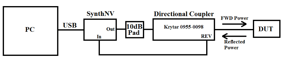
There is also a 1MHz – 4GHz broadband RF power detector enabled by the Analog Devices ADL5513 [11] which is fed through the SMA connector and 10dB built-in attenuator at [10]. This RF detector has up to 70dB of dynamic range and can measure up to +10dBm of RF power. The software will report real-time power measurements or can be calibrated to show gain over frequency between connector [6] and connector [10] which will give a basic ability to measure the performance of filters and other RF devices. The display will show RF power vs frequency, or gain vs frequency much like a lab quality network analyzer. By using an external directional coupler, there is also the ability to measure the return loss / VSWR of RF devices such as antennas.
Video courtesy of Adam VK4GHZ.
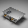
The Atmel microcontroller [8] is an ATmega32U4 and comes programmed with Windfreak Technologies proprietary firmware to allow basic control of the whole device. In conjunction with that, it also has the Atmel boot loader so that custom firmware can be loaded through USB by the end user. Many of the pins from the microcontroller go to .100″ inch headers (not included) spread throughout the PCB. These pins can be configured as generic digital I/O, A/D convertors, or PWM outputs. All the headers are on .100″ inch centers so perf board can be used for prototyping of special function daughter cards. Other functions that go to these headers are: SPI port, ISP (In System Programming) port, reset, boot load, and a basic FM analog connection to VCOs vtune port. If you want to use these functions you will need to install your own dual row .100″ inch headers.
USB communication is done via a virtual comm port directly to the microcontroller. Drivers are included with the software. The connector [7] requires a USB mini cable (not included).
Included with all of this are softcopies of the PC board schematics and a PCB reference designator map on the CD. This way you can see what bus wires are used to control the synthesizer chip and PA. You will also see what microcontroller pins are routed to headers. This helps with custom firmware development.
Note: Please look under the pink foam in the shipping box for the CD and instructions.
On board the PCB are 4 troubleshooting LEDs: one that shows USB power, two generic LEDs [3] from the microcontroller, and one that shows phase lock on the programmed frequency. The generic LEDs will blink differently with different commands. They will also show errors when the command is not understood. This helps with custom software development.
Flexible Applications
Compare this unit to other solutions worth thousands of dollars. We’ve invested hundreds of man-hours on software that you get to build upon for highly custom applications.
Some applications include:
- Eireless communications systems, microwave point to point backhaul radios
- Software Defined Radio (SDR), radar, Automated Test Equipment (ATE)
- EMC – radiated immunity pre-compliance testing, sweeping and hopping
- Scalar Network Analyzers (SNA)
- Complex waveform electronic warfare (EW)
- Phase Lock Loop (PLL) Synthesizer Design
- Local Oscillator (LO) replacement
- Hobbyist radio development.
For orders over 10 units discounts will apply. Request a quote via this Web Form.
Emails will be answered within 24 hours. Keep an eye on your SPAM folder. You will be given a lead time (usually ships right away) and a quote if you desire a large volume.