The SynthUSB3 thumb drive-sized RF signal generator is designed for an extremely high quality to cost ratio. These devices have set the bar on microwave radio frequency generators for quality, size, and price. As always, our products are designed, manufactured, and supported in the USA!
Tune any frequency between 12.5MHz and 6.4GHz in 0.01Hz resolution. Adjust calibrated amplitude in 0.2dB resolution up to +8dBm and across more than 50dB of range. The SynthUSB3 can also be used with an optional Breakout Board that allows connections to UART, trigger, and power.
Expect excellent performance and high reliability despite the SynthUSB3’s low cost.
After almost 10 successful years, the SynthUSBII gets a huge upgrade to SynthUSB3!
The Windfreak Technologies SynthUSB3 is a 12.5 MHz to 6.4 GHz software tunable RF signal generator and frequency sweeper controlled and powered by a device running Windows, Linux, or Android via its USB port. The SynthUSB3 also has nonvolatile on-board flash memory so it can be programmed to fire up by itself on any frequency, power, sweep or modulation setting (and combinations thereof) to run without a PC in the field. This makes for a highly mobile, low power, and lightweight solution for your RF signal generation needs.
Product Highlights
Amplitude calibrated for high amplitude accuracy
Great phase noise across all frequencies
0.01Hz tuning capability (0.1Hz default)
Up to 0.2 dB amplitude resolution
Up to +8dBm RF power
Linear (or %) sweeping and list mode hopping both frequency and amplitude
Control with USB or UART from your embedded microcontroller
Trigger sweeps, hops, pulses, etc.
Internally or externally modulate FM, AM, or pulse
Windows, Linux, and Android compatibility
Save all settings to the device for use without a PC
32 bit ARM processor onboard which is Arduino compatible
Designed and manufactured in the USA
For orders over 10 units discounts will apply. Request a quote here.
Emails will be answered within 24 hours. Keep an eye on your SPAM folder.
The SynthUSB3 was designed to work with a USB 2 port, or a USB 2 cable, which can be plugged into either a USB 2 or USB3 port. Use a USB 3 cable only when tapping into the UART and Trigger signals for 3.3V COM port control of the SynthUSB3 with your own microcontroller circuit. Using a USB 3 cable attached to a USB 3 port on a PC may have unknown consequences as the PC is not designed to see the SynthUSB3 UART signals and vv. See UART app note for UART usage instructions.
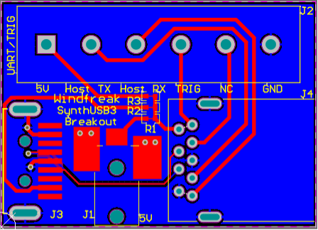
A USB 2 to USB 3 breakout adapter board is available for easier access to the UART and trigger, and modulation connections.
UART and Trigger signals are isolated with series 500 ohm resistors to protect the hardware.
2. Characteristics
2.1 Electrical Characteristics
Characteristic
Min.
Typ.
Max.
Unit
Notes
Supply Voltage
4.7
5
5.5
V
Suggested 300mA minimum
Supply Current
100
mA
0dBm RF at 1GHz
Standby Supply Current
10
mA
RF output OFF
RF Output Frequency Range
12.5
-
6400
MHz
Calibrated Frequency Range
12.5
6400
MHz
RF Output Power Maximum
8
dBm
See graph
RF Output Power Minimum
-50
dBm
See graph
RF OFF Output Power
-80
dBm
100% shutdown of RF section
RF Output Frequency Resolution
0.01
Hz
Default is 0.1Hz selectable by Channel Spacing Setting
RF Output Power Resolution
0.25
dB
Best Case – Non Monotonic
RF Output Impedance
50
Ω
Internal Reference Frequency
27
MHz
Internal Reference Tolerance
2.5
ppm
Trigger
-0.3
3.3
5
V
Internally pulled up 5V tolerant
UART
-0.3
3.3
5
V
3.3V native, 5V tolerant
RF Connector
Normally Polarized Female SMA
Weight
10
g
2.2 Thermal Operating Characteristics
Description
Min
Max
Unit
Notes
Operating Temperature
-40
70
°C
3. Software and Hardware
3.1 Open Source Software GUI
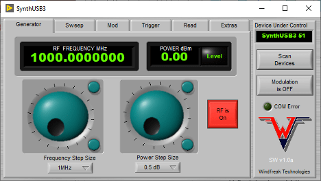
The included GUI is written in LabVIEW™ and source code vi’s are supplied with the purchase of hardware. Also supplied is a Windows installer for users that do not own the LabVIEW™ development environment. All functions of the hardware are accessible by the software. Custom software developers can download easy-to-use API documents on the website.
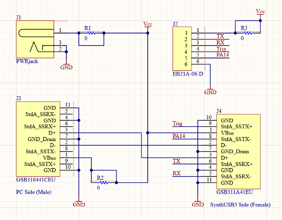
3.2 USB3 Connector Pinout
The USB3 connector is used in an unconventional way to allow access to UART and Trigger Signals. As mentioned above, avoid connecting this device directly to a USB3 port on your PC. Use a USB 2 extension cable instead.
USB3 Pin #
Signal Name
Description
1
VBUS
Power
2
USB D-
USB 2.0 differential pair
3
USB D+
4
GND
Ground
5
UART Tx
UART SynthUSB TX (hook to host RX)
6
UART Rx
UART SynthUSB RX (hook to host TX)
7
GND_DRAIN
Ground
8
N/C
To Processor I/O for future use
9
Trigger
Trigger Input
3.3 Recommended UART and Trigger Breakout Circuit
4. Typical Performance
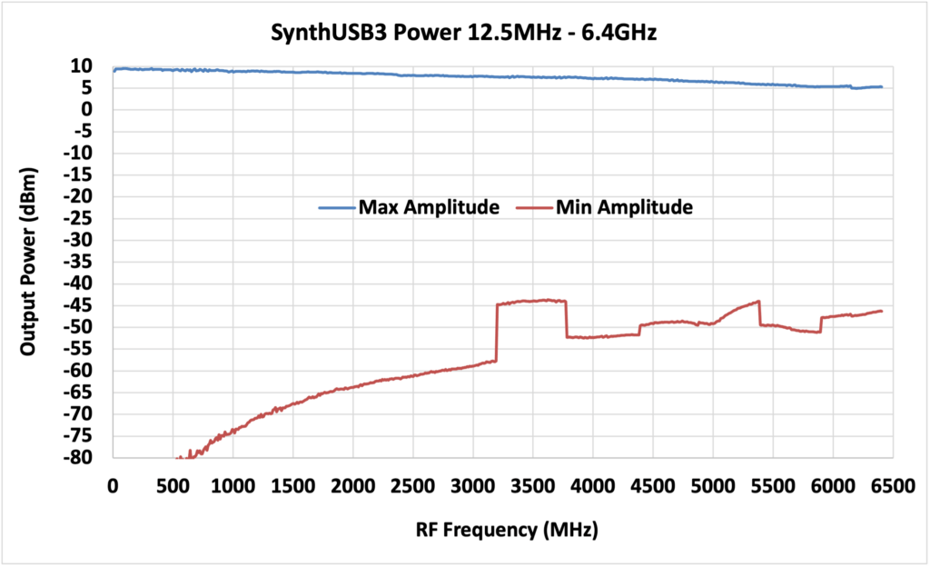
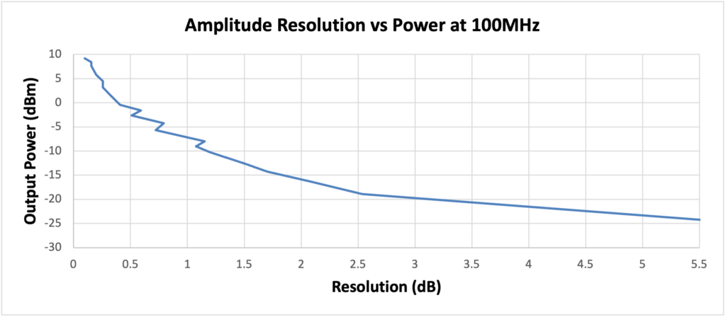
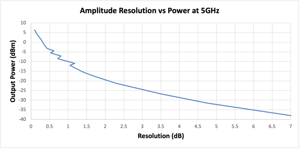
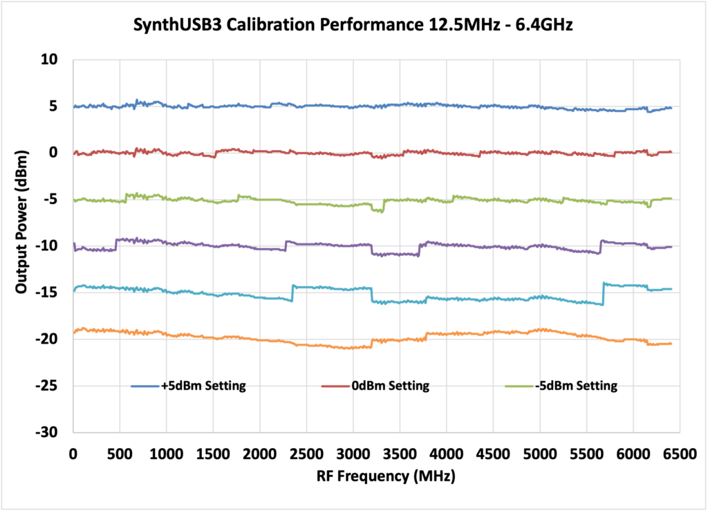
RF Output Power
The typical maximum and minimum output power of the SynthUSB3 is shown below. This graph is of unleveled operation at the maximum and minimum RF power settings.
Power levels are settable in 0.1dBm increments via software, but actual RF resolution and thus accuracy are dependent on amplitude. RF power setting resolution is non-linear with finer resolution at higher output powers. Onboard calibration is attained through a look-up table unique to each device. Device calibration is performed at the factory and stored in onboard flash memory. Calibration is good from 12.5MHz to 6.4GHz.
For example, in the Resolution vs Power at 100MHz chart above, resolution at +5dBm of output power is around 0.2dB, which would give a theoretical accuracy of +/- 0.1dB. With a setting of -20dBm the output power resolution is 3dB, which gives a theoretical accuracy of +/- 1.5dB.
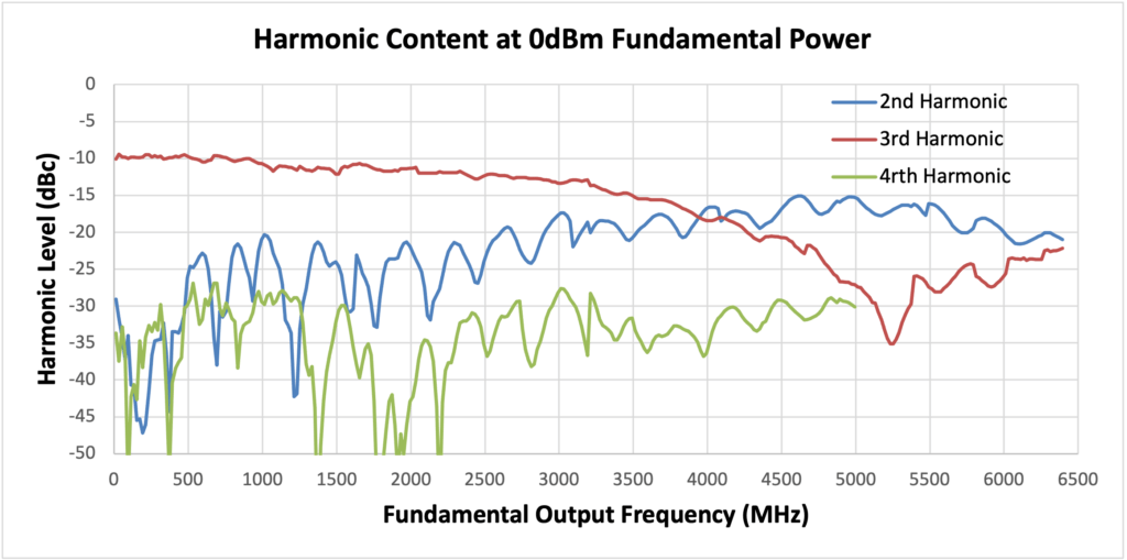
4.2 RF Output Harmonic Content
The typical SynthUSB3 harmonic distortion is shown below. This data is taken at a leveled fundamental power of 0dBm.
If lower harmonic levels are needed, Windfreak Technologies suggest the use of low cost SMA filters from Crystek and Minicircuits.
A mechanism for in-band fractional spur creation in all fractional PLL’s is the interactions between the RF VCO frequency and the internal 27MHz reference frequency. When these frequencies are not integer related, spur sidebands appear on the VCO output spectrum at an offset frequency that corresponds to the difference in frequency between an integer multiple of the reference and the VCO frequency. These spurs are attenuated when outside the loop filter which is roughly 50KHz wide.
Example if using the SynthUSB3 27MHz internal reference: For the fundamental VCO range of 3200MHz to 6400MHz the first integer boundary happens at 27MHz X 119 = 3213MHz, the next at 27MHz X 120 = 3240MHz and every 27MHz thereafter up to 6399MHz. Below the fundamental VCO band the spacing will be affected by the RF divider.
A typical case generating 3213.04MHz would give integer boundary spurs at a 40KHz offset at around 38dBc. A typical case generating 3213.40MHz would give integer boundary spurs at a 400KHz offset at around 52dBc. (These were measured with the reference doubler on and PLL ICP set at 15).
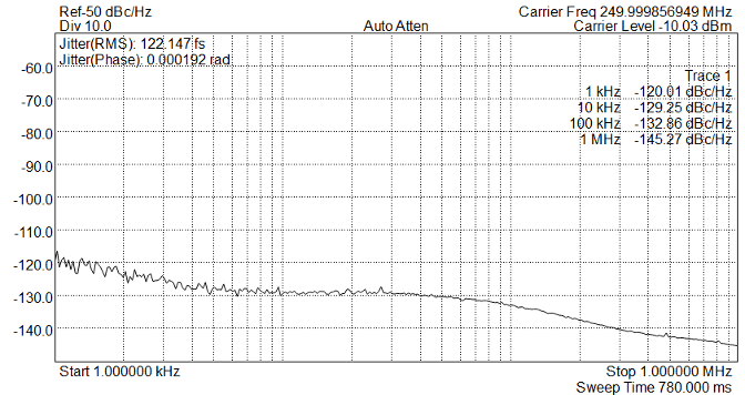
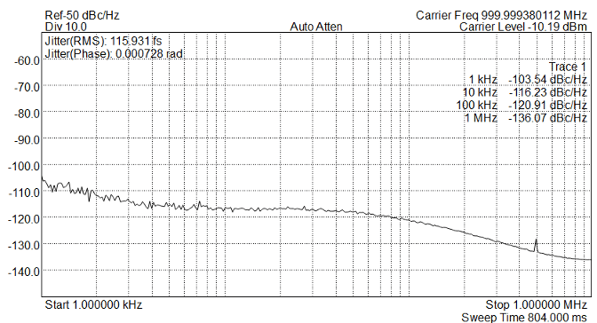
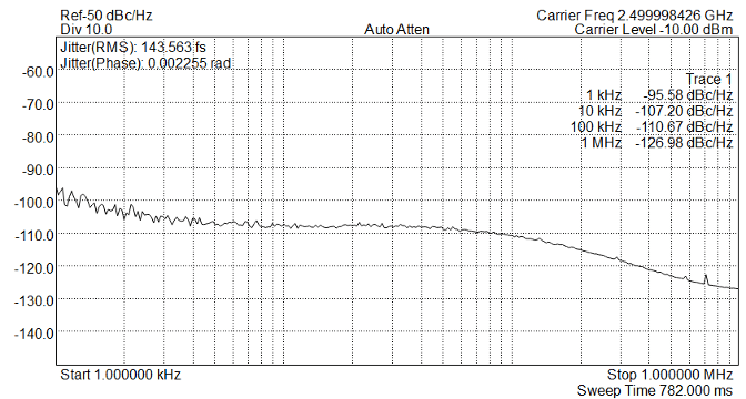
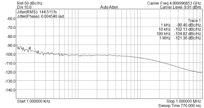
4.4 Phase Noise and Jitter
250MHz Phase Noise (27MHz Internal Reference with REF Doubler Enabled)1GHz Phase Noise (27MHz Internal Reference with REF Doubler Enabled)2.5GHz Phase Noise (27MHz Internal Reference with REF Doubler Enabled)5GHz Phase Noise (27MHz Internal Reference with REF Doubler Enabled)
5. Device Information
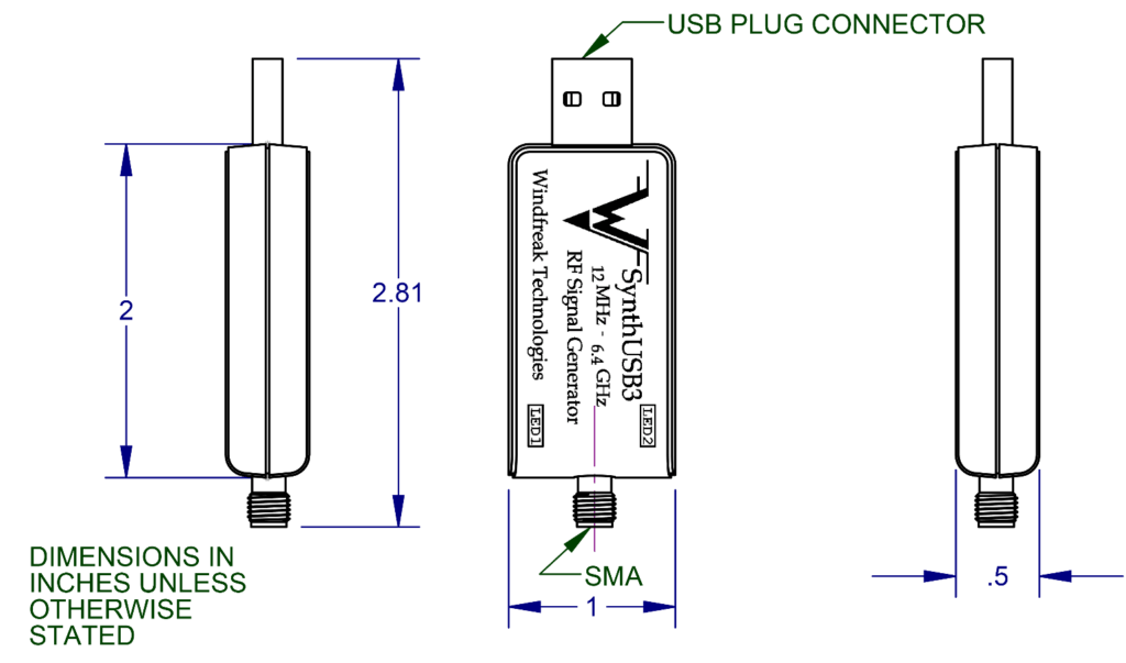
5.1 Mechanical Dimensions (2” X 1” X 0.5” plastic case)