USB RF Signal Generator Hardware and Software Features
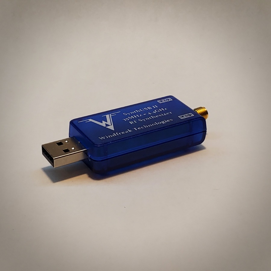
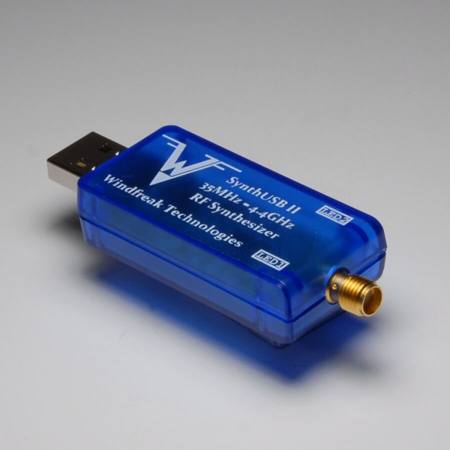
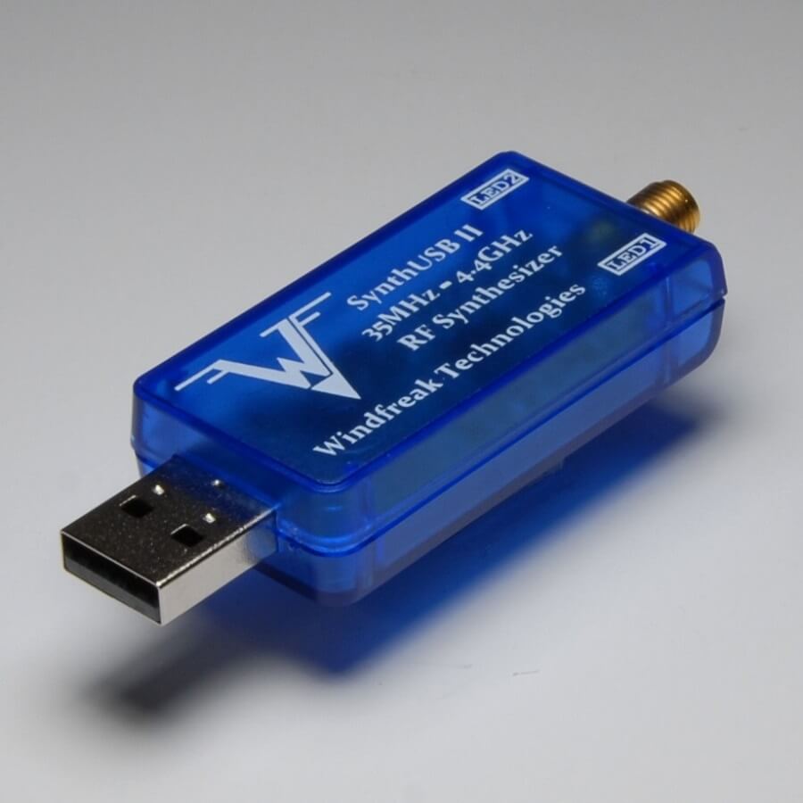
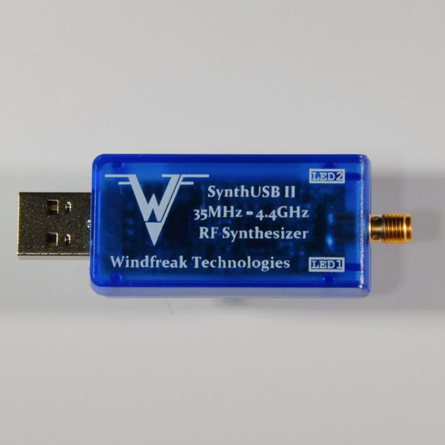
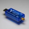
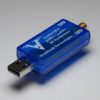
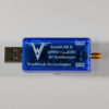
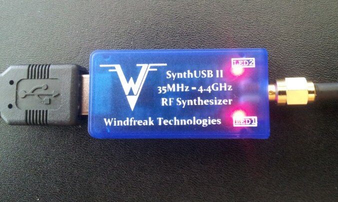
SynthUSBII Low Cost RF Signal Generator
Use this device as a generic RF signal generator in your test setup, or use it as a high quality local oscillator in your RF / microwave communication system.
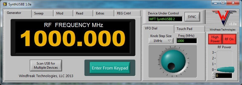
Shown below, the software is eloquently engineered giving professional performance at fractions the cost of a bench top generator.
You may enter data either with the touch pad, knob, directly with the PC keyboard, and also by clicking on arrows next to the controls.
RF single frequency generation tab.
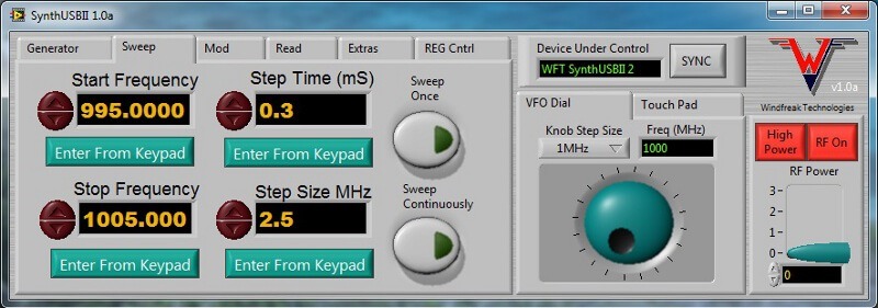
RF sweep generation tab. (Step as fast a 300uS per point. Resolution as low as 1KHz per step.)
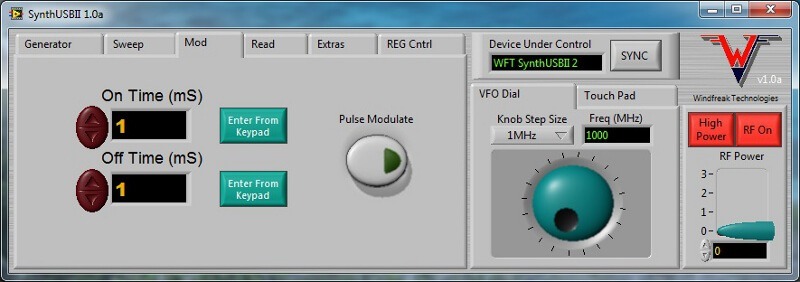
RF Pulse Amplitude Modulation tab. (Minimum pulse size and resolution is 1mS. Please see SynthNV for higher performance.)
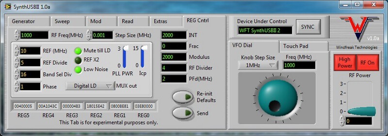
PLL Control tab. (Control some finer details of the ADF4351 chip to get higher accuracy or quality for a particular frequency.)
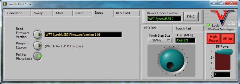
Extras tab. (Check SynthUSBII firmware version, save to SynthUSBII internal EEPROM memory Frequency, Power, Modulation and Sweep setup for standalone operation. Also poll every second for phase lock.)
RF power is controlled by two bits in the PLL chip. There is a total of 10dB of output power adjustment in 4 total steps. Please check out the SynthNV for more power and 1/2dB steps.
The software is easy to install and use. It can control multiple devices based on programmed serial numbers, tune a RF CW frequency, run a RF sweep, Pulse Modulate, save many settings to EEPROM, and fine tune the PLL registers for experienced users. Control is very similar to a bench top signal generator. It is also touch panel friendly.
This software was written in Labview and the open source code is included so that you can modify and enhance any way you see fit for your own use. Please do not distribute. If you don’t own Labview, you will also get an executable that will install standalone and run on a PC. If you want to write your own software, it is best to get Labview and reverse engineer the Windfreak Labview source code. Labview is available with a free 1 month trial from National Instruments. All source code is sent on CD “saved as” using the latest version of Labview Basic. The device is easy to talk to via 1 simple command character followed program data. For example, setting frequency is done by sending “f1000.0” (without the quotes).
Click here to see the format for serial communications via the proprietary Windfreak firmware:
Serial Communication
Click here for the operating instructions included with the device:
Instructions
The Hardware:
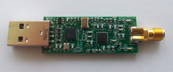
The SynthUSBII is made in the United States from parts purchased in the USA via manufacturers certified vendors.
The technology is based on Analog Devices ADF4351 chip seen here:
Click here for the ADF4351 Datasheet
You can expect high quality RF performance at the RF connector similar to the specs in the datasheet.
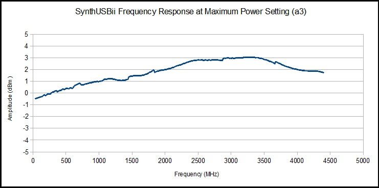
RF power (max) into a 50 ohm load is similar to this:
RF generator accuracy is based on an onboard 2.5ppm 10MHz crystal oscillator. All parts on the PCB are specified to operate from -40 to +85C.
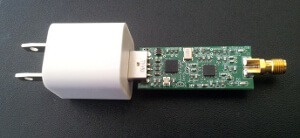
The synthesizer will run off USB power. It will also run standalone without a PC connected if you have a USB power supply similar to an iphone charger. The required voltage is 5 volts DC at <200mA.
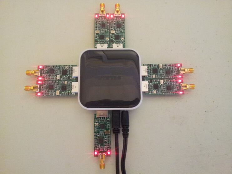
You can also run multiple SynthUSBII devices from a powered USB hub. The below picture is taken without the plastic cases for a better fit on this particular Belken hub.
You can run them all with one GUI, or run one GUI for each device for quick individual adjustments. The spectrum plot to the right was taken with a crude cut wire antenna. Hence the unequal powers in each carrier.
The Atmel microcontroller on board is an ATmega32U2 and comes programmed with Windfreak Technologies proprietary firmware to allow basic control of the whole device. In conjunction with that, it also has the Atmel boot loader so that custom firmware can be loaded through USB by the end user.
USB communication is done via a virtual comm port directly to the microcontroller. Drivers are included with the software. The SynthUSBII can plug straight in to your PC. A USB type A extension cable is recommended but not included.
Included with all of this are softcopies of the PC board schematics and a PCB reference designator map on the CD. This way you can see what bus wires are used to control the synthesizer chip and PA.
Note: Please look under the pink foam in the shipping box for the CD and instructions.
On board the PCB are 2 troubleshooting LEDs: LED1 shows USB power upon startup, and LED2 shows phase lock on the programmed frequency. LED1 also blinks during USB communication. Both LEDs blink when a USB command is not understood. This helps with custom software development.
Compare this unit to other solutions worth thousands of dollars. We’ve invested hundreds of man hours on software that you get to build upon for highly custom applications.
Some applications include: wireless communications systems, microwave point to point backhaul radios, Software Defined Radio (SDR), radar, Automated Test Equipment (ATE), sweeping and hopping, electronic warfare (EW), Phase Lock Loop (PLL) Synthesizer Design, Local Oscillator (LO) replacement, and hobbyist radio development.
For orders over 10 units discounts will apply. Request a quote via this Web Form. Emails will be answered within 24 hours. Keep an eye on your SPAM folder. You will be given a lead time (usually ships right away) and a quote if you desire large volume.
IN STOCK. Ships within 2 business days.

