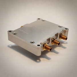
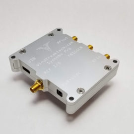
SynthNV PRO: 12.5MHz – 6.4GHz RF Signal Generator Plus RF Detector
$1,199.00
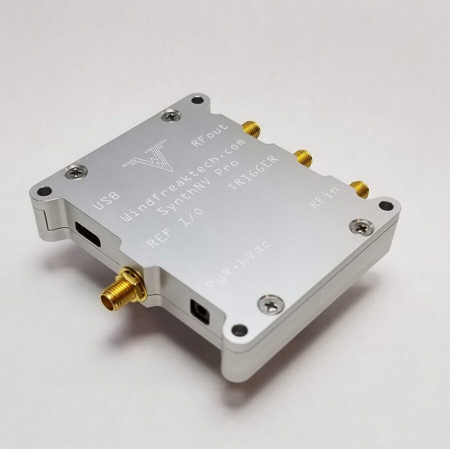
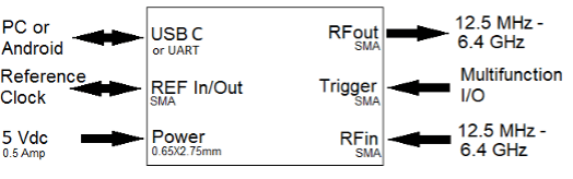
The Windfreak Technologies SynthNV Pro is a 12.5 MHz to 6.4 GHz software tunable RF signal generator and frequency sweeper controlled and powered by a device running Windows, Linux, or Android via its USB port. The SynthNV Pro also has a broadband RF Detector port allowing it to measure RF power in dBm up to 6.4GHz and over 50dB of range. The RF generator side has a multiband agile switching low pass filter to help attenuate output harmonics.
Key Features:
Highly calibrated 12.5 MHz to 6.4 GHz RF Signal Generator plus broadband RF detector and power meter
16 band high-speed switching harmonic filter on its output that attenuates harmonics up to 60 dBc
Low harmonic distortion
100uS large frequency steps (phase lock to phase lock)
0.1Hz frequency step size
0.01dB amplitude step size
0.01 degree output phase adjust
Internal Operating Temperature: -40C to +85C (-40F to +185F)
The SynthNV Pro also has nonvolatile on-board flash memory so it can be programmed to fire up by itself on any frequency, power, sweep or modulation setting (and combinations thereof) to run without a PC in the field. This makes for a highly mobile, low power, and lightweight solution for your RF signal generation needs.
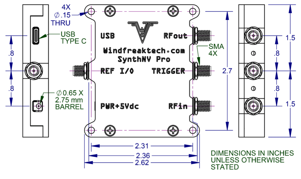
Please note: As of 8/23/2023 and Serial #488 we have moved to a new mechanical design. Click here for the dimensions.. No other specs have changed.
In Stock. Ships within 5 business days.
We've Got You Covered:
No Hassle Refunds - 90 Day Money Back Guarantee!
Secure checkout via Credit Card, PayPal, and Venmo
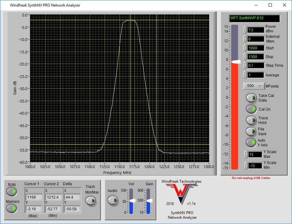
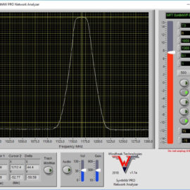
The SynthNV PRO is a highly calibrated 12.5 MHz to 6.4 GHz RF Signal Generator plus broadband RF detector and power meter. The SynthNV Pro accomplishes Scalar Network Analysis for both through and reflected (requires external 3rd party directional coupler) responses of RF devices such as filters, amplifiers, antennas, cavities, and matching networks. Frequency set to RFout – then measure RFin sweeps run at 150uS per point. Notably, the SynthNV PRO also has a 16 band high-speed switching harmonic filter on its output that attenuates harmonics up to 60 dBc.
Product Highlights:
Low harmonic distortion
100uS large frequency steps (phase lock to phase lock)
0.1Hz frequency step size
0.01dB amplitude step size
0.01 degree output phase adjust
Instantaneous, Peak, and Average on power measurement input
Built-in frequency dependent calibrations on both TX and RX
FM, AM, and Pulse via internal and external modulations
500 point frequency and power hop lookup table
Sweep with constant frequency step, or percentage
Sweep or step modulated wave forms
Powerful external triggering
Onboard speaker can change pitch with RF input power (bug sniffing or audible tuning feedback)
Network Analyzer app also has audio frequency selective feedback
Possible option for an OLED display (TBD)
Option for UART control (through USB-C connector)
Plans for USB-C adapters allowing RS485, RS232, Wifi and Ethernet to UART bridges
Fast 32 bit ARM processor with floating point math unit
12 bit ADC for the power detector < 0.05dB resolution
Digital temperature compensation
Shielded RX for better isolation
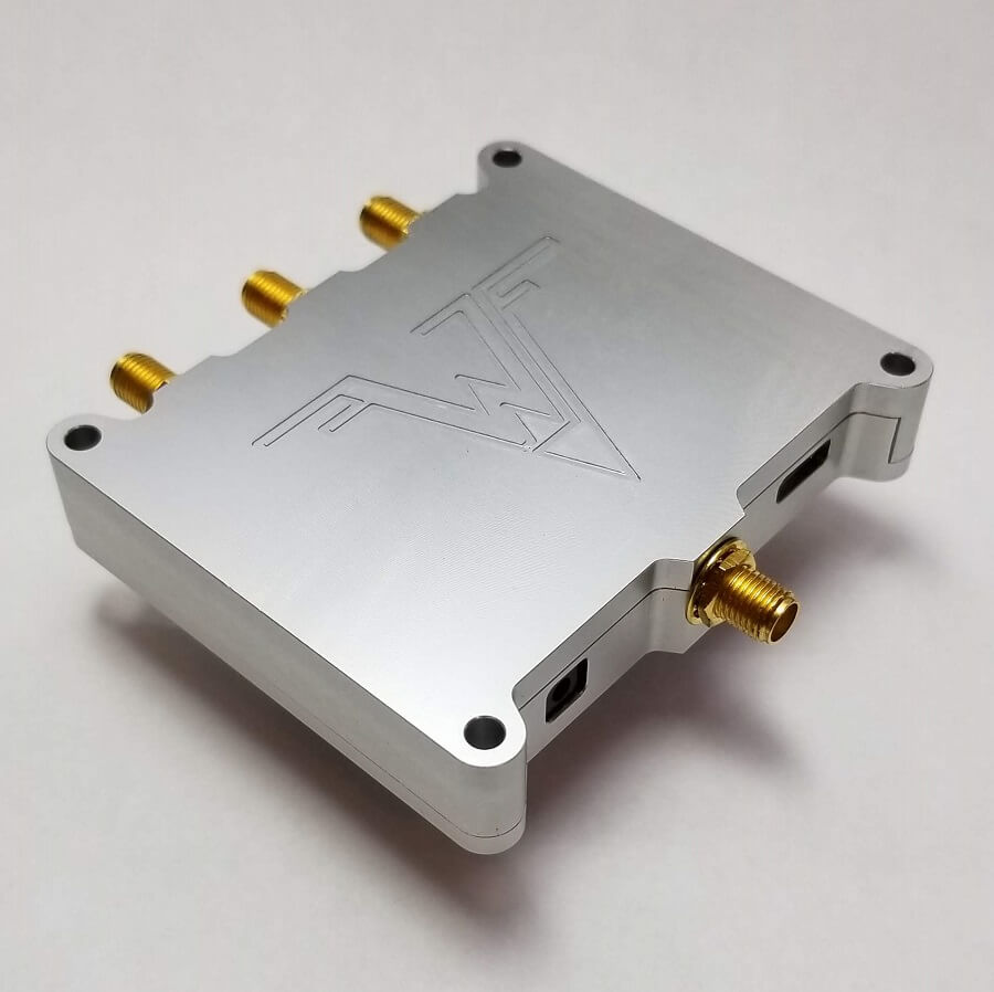
Stack-able high quality milled aluminum enclosure
Low power draw via power connector or USB type C
Windows open source GUI or command line Linux and Android control
Designed and manufactured in the USA with maximized value / cost ratio
Contact us for custom firmware and hardware options
The SynthNV Pro was designed to work with, and ships with, a USB 2 cable. Use a USB 3 cable only when tapping into the UART signals for 3.3V COM port control of the SynthNV Pro with your own microcontroller circuit. Using a USB 3 cable attached to a USB 3 port on a PC may have unknown consequences as the PC is not designed to see the SynthNV Pro UART signals and vv. See UART app note for UART usage instructions.
2. Characteristics
2.1 Electrical Characteristics
Characteristic
Min.
Typ.
Max.
Unit
Notes
Supply Voltage
4.7
5
5.5
V
Suggested 1A minimum
Supply Current
250
mA
Standby Supply Current
60
mA
RF output OFF
RF Input / Output Frequency Range
12.5
-
6400
MHz
Calibrated Frequency Range
12.5
6400
MHz
RF Output Power Maximum
6
11
15
dBm
See graph
RF Output Power Minimum
-45
dBm
See graph
RF Input Power Range
-40
15
dBm
Max is +20dBm before damage
RF OFF Output Power
-80
dBm
100% shutdown of RF section
RF Output Frequency Resolution
0.1
Hz
Default is 100Hz selectable by Channel Spacing Setting
RF Output Power Resolution
0.01
dB
RF Phase Resolution
0.01
°
** See note 1
RF Output Impedance
50
Ω
Internal Reference Frequency
10 or 27
MHz
Selectable
Internal Reference Tolerance
2.5
ppm
External Reference Frequency
10
-
100
MHz
Keep phase comparator less than 100MHz
External Reference Level
-10
10
dBm
Keep below 3.3Vpp
Trigger
-0.3
3.3
V
Internally pulled up
UART
-0.3
3.3
5
V
3.3V native, 5V tolerant
Note 1: Phase tuning speed, phase resolution and carrier frequency are inter-related. Phase tuning speed slows as RF carrier frequency and Channel Spacing settings decrease. Smaller Channel Spacing will have higher phase and frequency resolutions but slower phase tuning speed. Going below 100MHz carrier with smaller Channel Spacing than 100Hz may be prohibitively slow and/or erratic.
2.2 Thermal Operating Characteristics
Description
Min
Max
Unit
Notes
Operating Temperature
-40
50
°C
Without airflow or heatsinking
Operating Temperature
-40
75 Internal
°C
Query internal temperature sensor with software and keep below 75C with airflow, heat sinking or limited duty cycle.
3. Typical Performance
3.1 RF Output Power
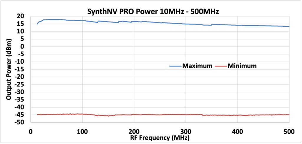
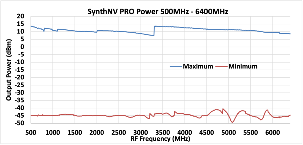
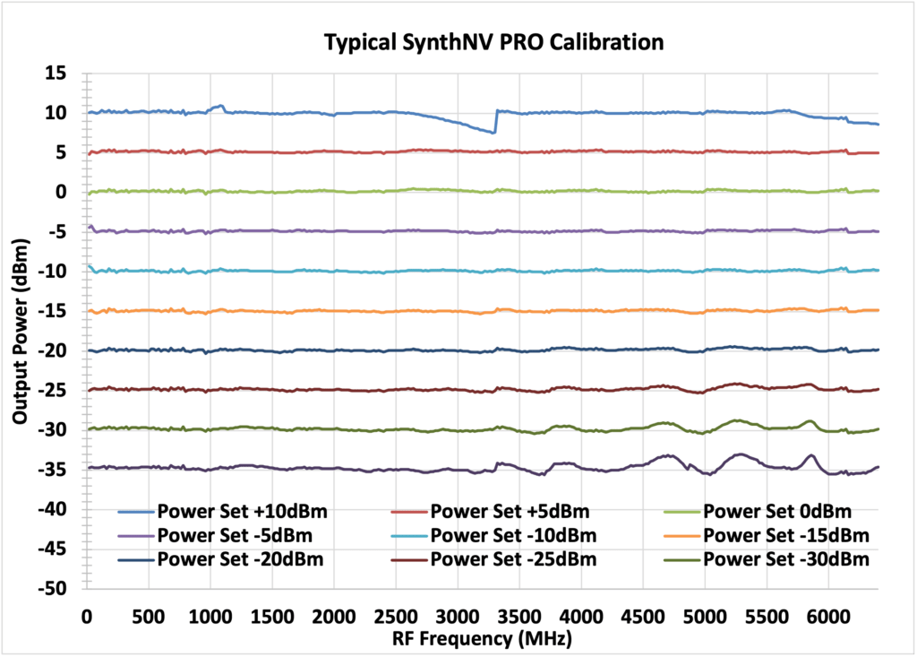
The typical output power of the SynthNV Pro is shown below. This graph is of unleveled operation at the maximum gain setting of the output and -45dBm for the minimum setting. Settings between these two levels will be controlled and uncalibrated levels can be attained below -45dBm. RF output power and frequency can be set independent of each other. Power levels are settable in 0.01dBm increments. On-board calibration is attained through a look up table. Device calibration is performed at the factory and stored in onboard flash memory. Calibration is good from 12.5MHz to 6.4GHz. All parts of the signal chain have high quality voltage regulation, and the D/A driving the VGA have a 1% voltage reference controlling their outputs. Maximum power transitions in the graphs below are due to switch points in the switchable output harmonic filter and are not user controllable.
Note: +10dBm setting hitting max power limit in spots
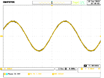
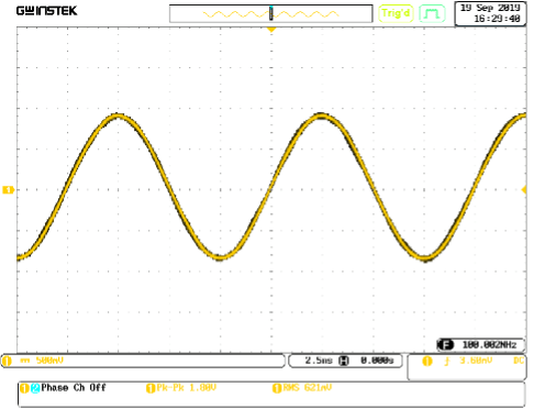
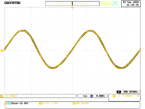
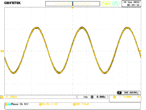
3.2 RF Output Harmonic Content
The typical SynthNV Pro harmonic distortion is shown below for the second and third harmonics. This data is taken at a leveled fundamental power of 0dBm.
If lower harmonic levels are needed, Windfreak Technologies suggest the use of low cost SMA filters from Crystek and Minicircuits.
A mechanism for in band fractional spur creation in all fractional PLL’s is the interactions between the RF VCO frequency and the internal 27MHz, internal 10MHz or arbitrary external reference frequency. When these frequencies are not integer related, spur sidebands appear on the VCO output spectrum at an offset frequency that corresponds to the difference in frequency between an integer multiple of the reference and the VCO frequency. These spurs are attenuated when outside the loop filter which is 30KHz wide. By having two selectable internal reference frequencies of 10MHz and 27MHz the problem is eliminated by switching reference frequencies when working around a boundary.
Example if using the SynthNV Pro 27MHz internal reference: For the fundamental VCO range of 3200MHz to 6400MHz the first integer boundary happens at 27MHz X 119 = 3213MHz, the next at 27MHz X 120 = 3240MHz and every 27MHz thereafter up to 6399MHz. Below the fundamental VCO band the spacing will be affected by the RF divider. If the desired VCO operating frequency is 3213.01MHz this would give spurs 10KHz on either side of the carrier that may be unacceptable. In this case, using the 10MHz reference would be suggested since its closest integer boundary is at 3210MHz. Spurs 3MHz away will be attenuated to satisfactory levels by the loop filter.
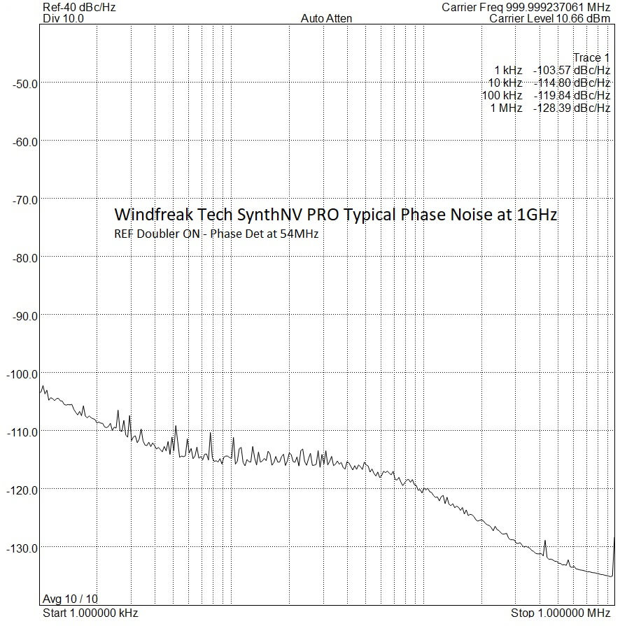
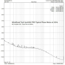
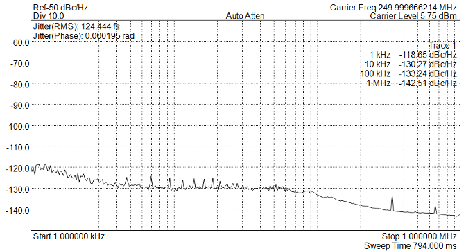
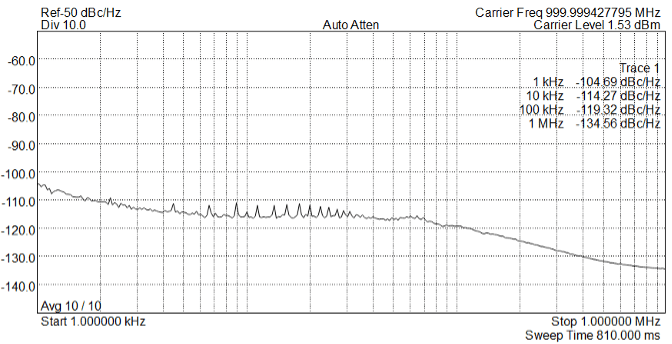
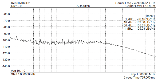
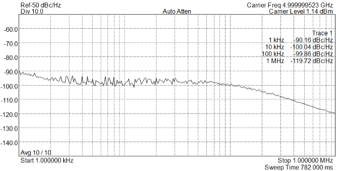
3.4 Phase Noise and Jitter
250MHz Phase Noise (27MHz Internal Reference with REF Doubler Enabled)1GHz Phase Noise (27MHz Internal Reference with REF Doubler Enabled)2.5GHz Phase Noise (27MHz Internal Reference with REF Doubler Enabled)5GHz Phase Noise (27MHz Internal Reference with REF Doubler Enabled)
3.5 RF Power Detector
The power detector on the SynthNV Pro is comprised of a broadband log detector that is calibrated from 12.5MHz to 6.4GHz. Between it and the input SMA connector is a 10dB pad designed to give a broadband 50 ohm match, plus allow higher powers (up to 15dBm) into the detector. Between the log detector and the analog to digital converter are 3 selectable circuits for advanced users. The default is an instantaneous sample which samples the RF power at an indeterminate time quickly after its initiated. The other two involve 1) a resistor/capacitor averaging circuit and 2) a diode/capacitor peak detector circuit which is uncalibrated due to its diode voltage drop. The last two circuits specifics are TBD but may help in application with high peak to average RF power.
The detector knows nothing about the frequency content of the signal it is receiving. It only measures power and the power it measures is a summation of all content across its working spectrum. (It is not a spectrum analyzer.)
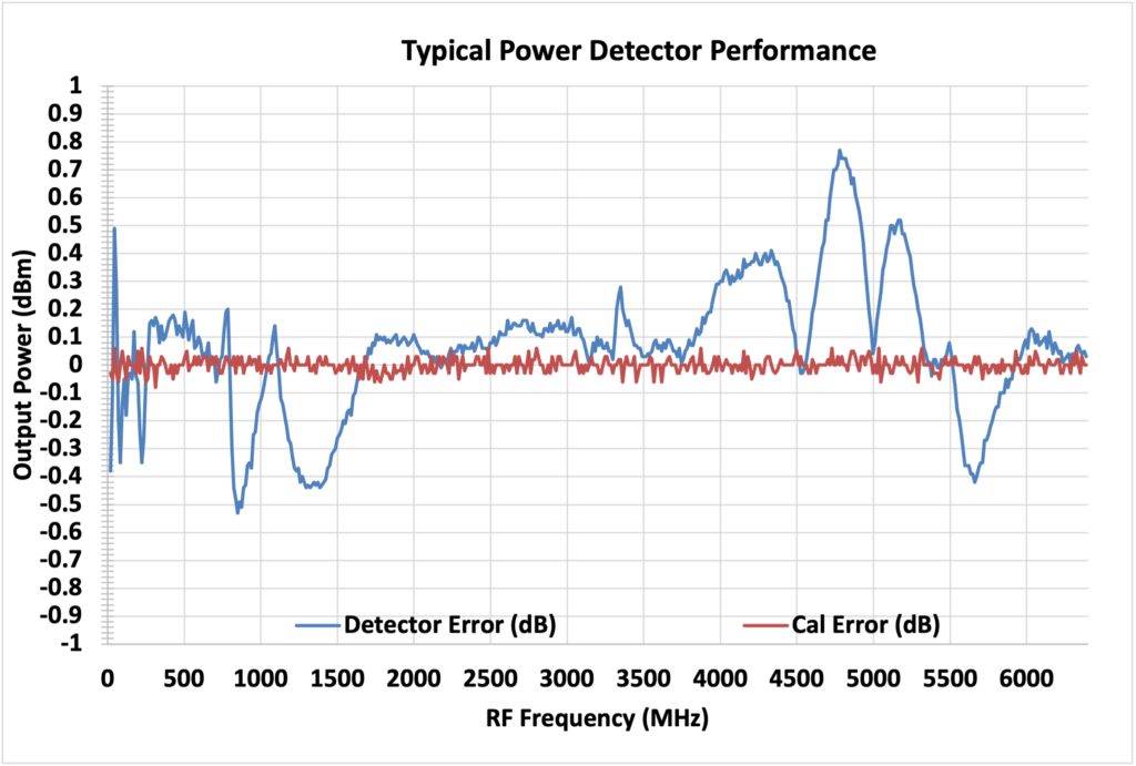
In closed systems using the signal generator and power detector, it is possible to know the frequency the detector is reading, plus calibrate out any amplitude error. This allows the device to function as a scalar network analyzer which can be used to sweep the frequency response of amplifiers, attenuators and filters. Its also possible to use an external directional coupler to measure the return loss of those types of devices.
The plot below shows a typical raw Detector Error trace relative to the calibrated output power of the signal generator side (which also has some embedded error). The Cal Error trace shows the error after a software calibration is performed with the supplied GUI Network Analyzer application.