Antenna Beam Steering
RF signal generators can be an easy tool used to start testing and understanding concepts of phased array antennas and beam steering. Specifically, the SynthHD and SynthHD Pro RF signal generators have dual independent channels that allow independent control of frequency, phase and amplitude on each channel. If both channels are set to the same frequency, the phase can be adjusted in fine steps across a full 360 degrees.
An Explanation of Antenna Beam Steering and its History
In its simplest form, antenna beam steering would be accomplished by a directive antenna being driven by a servo motor to steer the RF radiation and reception in the desired direction. You can see this done on pleasure boat radar using a rotating radar antenna, usually called an open array radar. The same thing happens with most radar on boats, but some are under a radome, so the spinning antenna is protected and unseen. Pulses or chirps are transmitted at the speed of light and bounce off targets. They are received while being very accurately timed. The radar will then use the time of flight to draw a plot of echoes reflecting back telling the navigator where land, rainstorms and other hazards are around them, significantly increasing marine safety. Of course, this extends to military, weather and other radar applications.
It also extends outside of radar applications. In Figure 1 below, the Simrad antenna on the left is the rotating marine radar. The radome on the right contains a satellite TV receiver which has a gimballed antenna inside that steers itself with the boat’s movement. The antenna constantly aligns itself with the satellite signal for uninterrupted radio frequency reception.

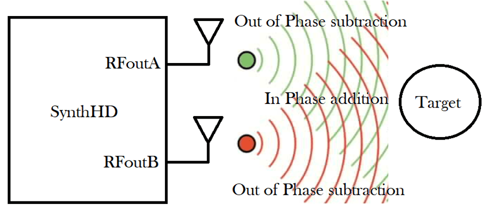
The performance of this method depends on the RF wavelength versus the physical separation of the antennas. In the example above the antennas are emitting in-phase signals created by the Windfreak Technologies SynthHD. The septum extending out between the two antennas is the zone where signals are adding together, which gives maximum radiation to the target. Outside of that zone the signals begin to destructively interact and thus receive less RF energy.
Phased Array Antennas Driven By Dual Channel RF Signal Generators
By tuning the phase of either RFoutA or RFoutB, the in-phase addition zone can be steered to follow the target if it moved up or down. If RFoutA is tuned 180 degrees out of phase versus RFoutB and has the same amplitude, the waves would completely subtract so that the target would receive little RF energy. Most RF energy the target receives would be reflections from objects around the transmitter and target. This is called multi-path interference.
An array of more than two antennas all driven by different phases can give better performance and quite often are printed in copper on a single dielectric substrate. This can allow higher directivity, fewer radiational side lobes and 3 dimensional steering or scanning.
A Fun Experiment
Set up the experiment in the picture above. Tune RFoutB off frequency by 0.1Hz. Measure the target signal strength with a spectrum analyzer and watch how the amplitude varies with time. Now adjust the distance between antennas and watch how the pattern changes. The pattern will repeat itself 1/0.1Hz = every 10 seconds. Easily automate this process with Labview since Windfreak products come with Labview source code which can be easily cut and pasted into custom applications.
