We pride ourselves in designing, building, and selling high value radio frequency products that are thoroughly evaluated and tested. All of our products go through rigorous testing before releasing to our customers. Our devices have proven to be very reliable. In rare cases, we have had a product come back for repair caused by output amplifier failures. In this post, we explain the testing process we go through to ensure our high-quality products and the two reasons for output amplifier failures.
How We Test and Verify Reliability of RF Output
To verify that our RF output design is reliable, we submit several production units of each model to two long-term tests.
- Full frequency range sweeping is performed on the output at maximum RF power into an open load and a short load. This test is usually run for a full week.
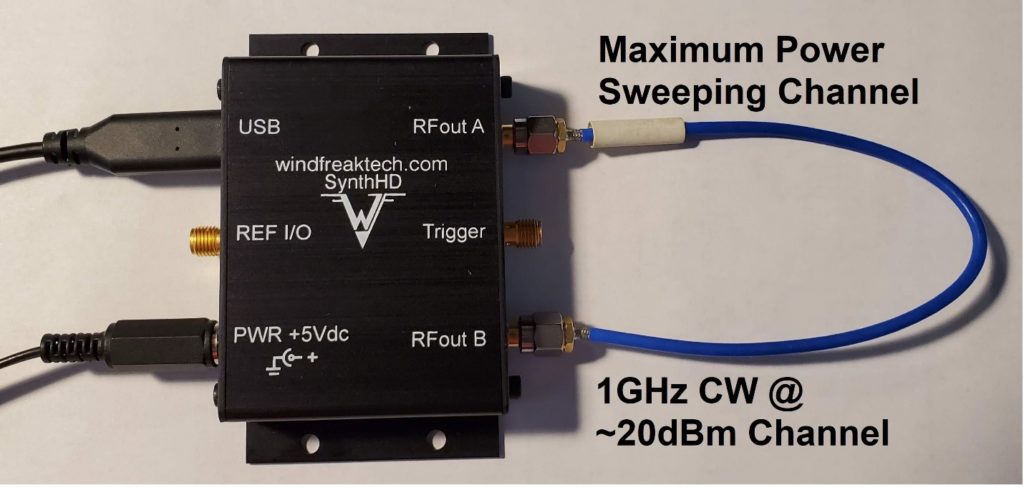
- Full frequency range sweeping at maximum RF power is performed directly into the output of another RF Signal Generator while that generator is generating approximately +20dBm of RF output power at 1GHz. In the case of the SynthHD, both channels are directly connected via a short SMA with each channel configured as above. See below. This test is usually run for a full week.
To date, we currently have no RF testing products that have failed these tests.

Reasons for Output Amplifier Failures
The most common reason for failure is output amplifier burnout. We have determined that output amplifier failures, in general, are caused by the following issues.
1. Improper Connections to Customer Equipment
We find that making sure customers have proper connections in place can help minimize output amplifier burnout. We explain experimental and bi-directional amplifier failures below and how to avoid these issues.
Experimental Amplifier Failures

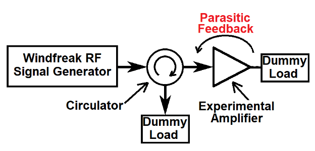
Quite often our RF Signal Generators are used in experimental situations. One situation is the design and test of RF power amplifiers. During the beginning stages of RF amplifier design it’s not uncommon to first have a high power RF oscillator (instead of an amplifier) due to too much feedback in the circuit from parasitic influences. In this case, it’s possible that large RF voltages are present on the output of the RF Signal Generator coming back from the input of the experimental RF amplifier.
Even if the amplifier does not oscillate on its own with no connection, the input return loss of the amplifier could be positive which would expose the RF Signal Generator to large RF signals. The protection for this situation would be a high power isolator (or circulator) between the RF Signal Generator and the experimental amplifier.
Measuring the power from the circulator into the dummy load will give you an idea of the return loss or oscillation of the experimental amplifier. After large signals are ruled out, use traditional methods to verify good return loss at all frequencies for the experimental amplifier design.
Bi-Directional Amplifiers Failure

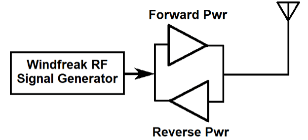
Another situation that has come up more than once is in the DAS (Distributed Antenna Systems) industry where customers are using an RF Signal Generator to test radiated power through a repeater with forward and reverse amplifiers.
The technician would transmit through the forward amplifier and test RF power at various places in a building that is radiated from the antenna shown. The problem is that uncontrolled RF can come into the antenna, go through the reverse power side, and burn out the RF Signal Generator.
For example, a transmission like this could simply come from the cell phone in the technician’s pocket, or a TV station tower down the road. A solution would be to somehow disable the reverse amplifier or use a circulator (or isolator) shown in the circuit above between the RF Signal Generator and the amplifier.
2. Electrostatic Discharge Failures
ESD is well documented in the electronics industry. It may not be stressed strongly enough in academia. Typically, RF Signal Generator ESD failures come from college campuses or other industries where the device may be transported outside of the lab environment or used without proper ESD procedures. These devices are easily transportable considering the small size. The problem is exacerbated by cool dry climates.
There are many ESD training videos on Youtube that are worth watching. Here is one:

Another example could be if the RF Signal Generator feeds another open electronic circuit that is being hand tuned for a good RF match, but the person doing the tuning is not strapped in with an ESD strap to the local equipment ground plane. Touching the open circuits could feed hundreds or thousands of volts directly into the output of the RF Signal Generator.
ESD Safe Shipping
We ship each device with a ziplock ESD safe bag. It is suggested that this bag is kept and used to transport the RF Signal Generator, even across a lab. Before taking the RF Signal Generator out of the ESD bag, use a static strap that clips onto the ground of the equipment you will be using in the test setup. If this is impossible to do, at a minimum touch a screw lead on the equipment to hopefully dissipate any charge before you hook it up.
Any Questions About Testing and Reliability?
If you have any further questions about reliability, please contact me at dgoins@windfreaktech.com.
