SynthHD PRO (v2): 10MHz – 24GHz Dual Channel Microwave RF Signal Generator
$2,999.00
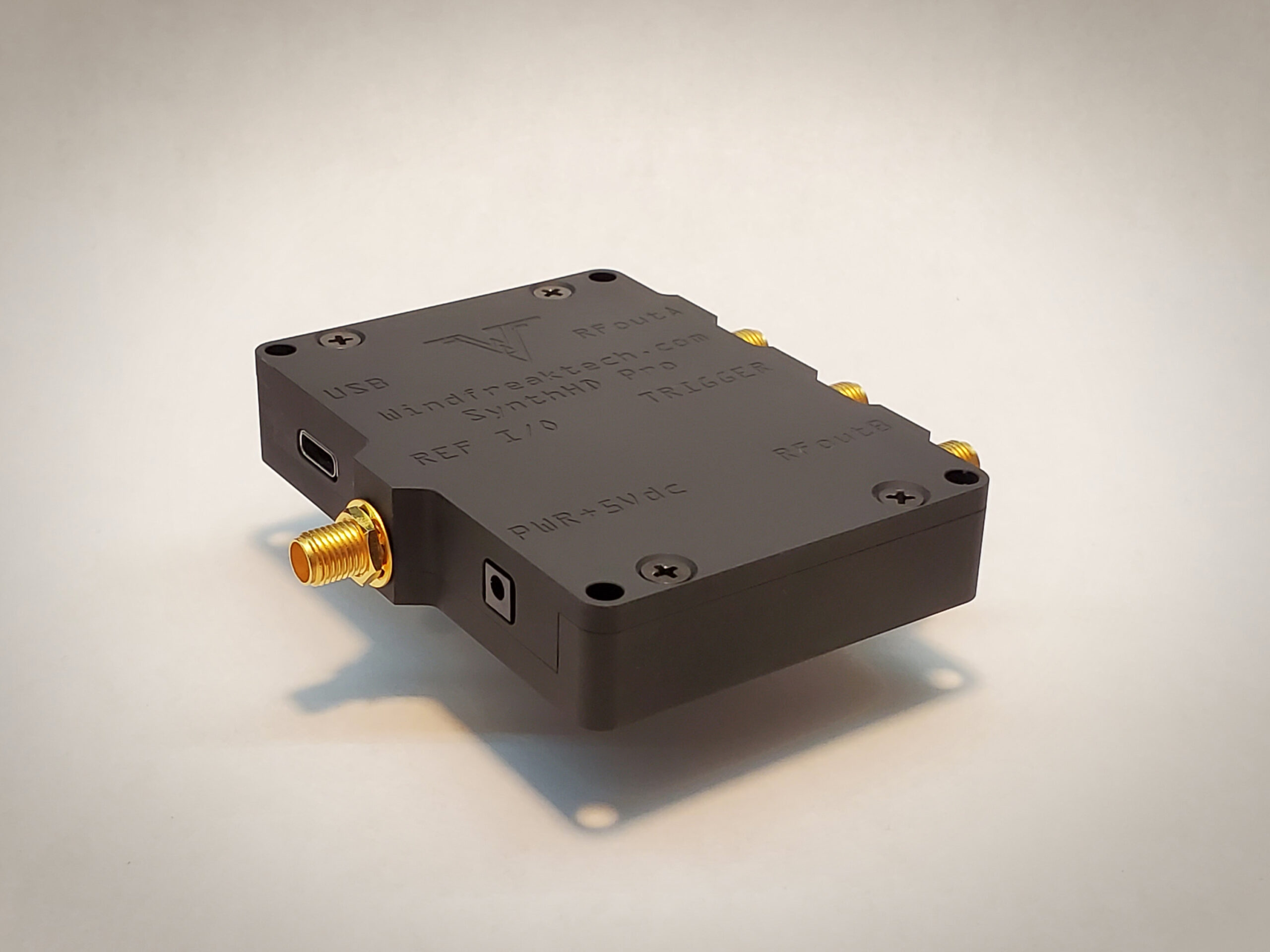
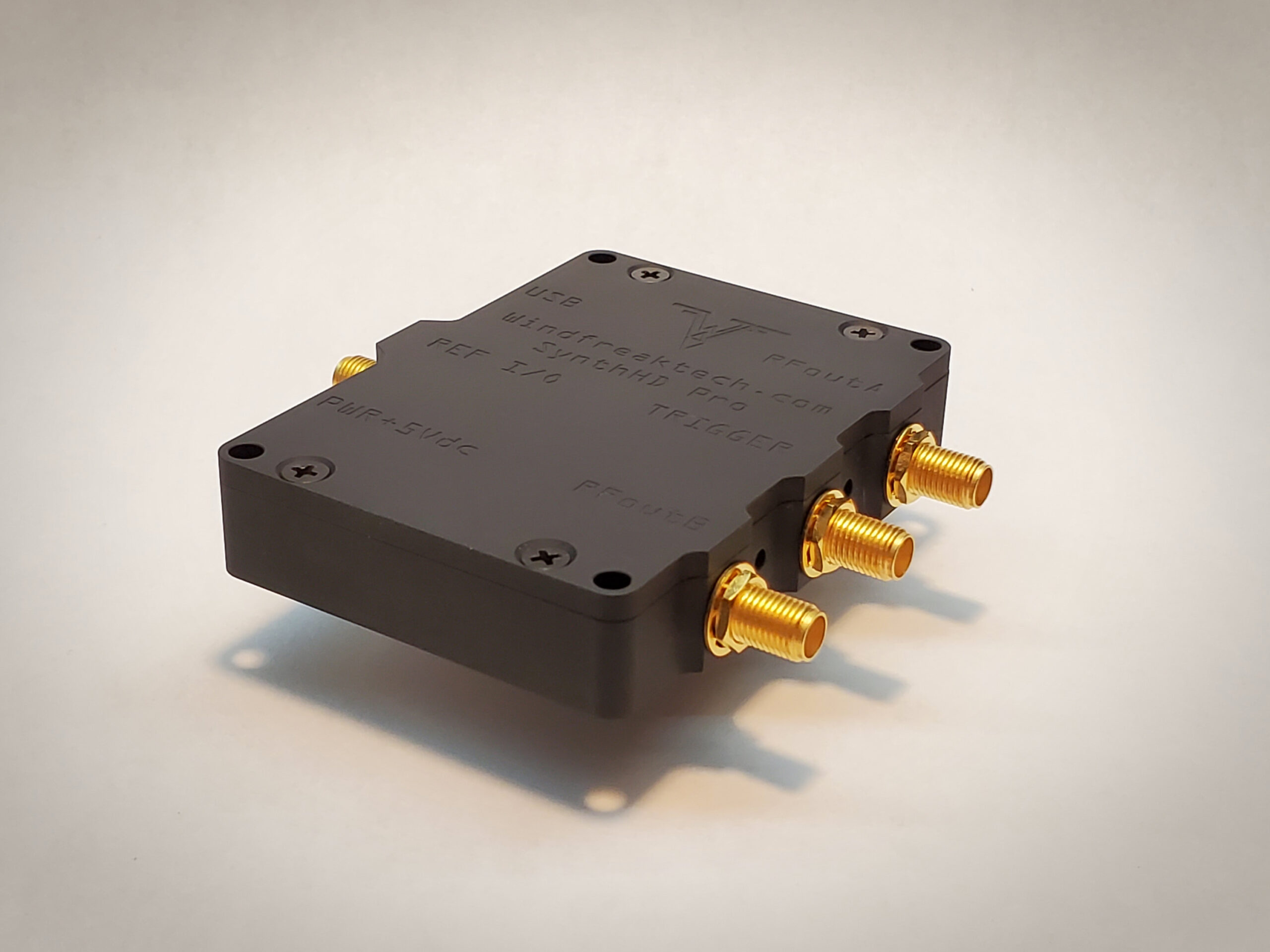
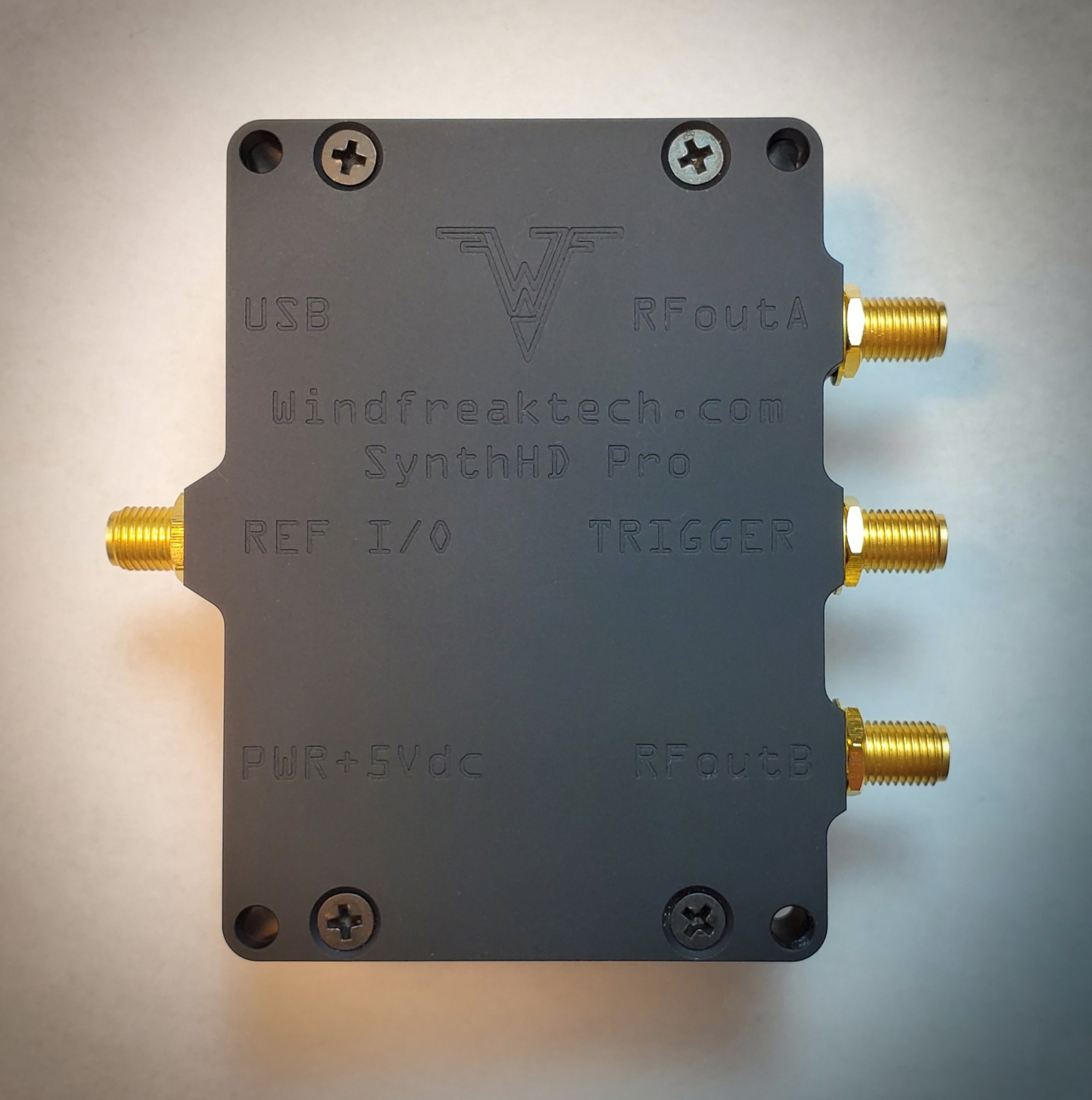
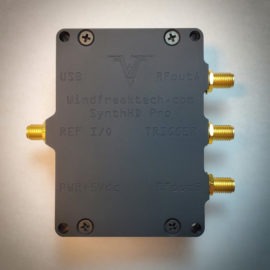
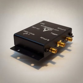
The Windfreak Technologies SynthHD PRO is a 10 MHz to 24 GHz dual channel software tunable RF signal generator and frequency sweeper controlled and powered by a device running Windows or Android via its USB port.
Key Features:
10 MHZ to 24 GHZ in 0.1 Hz steps
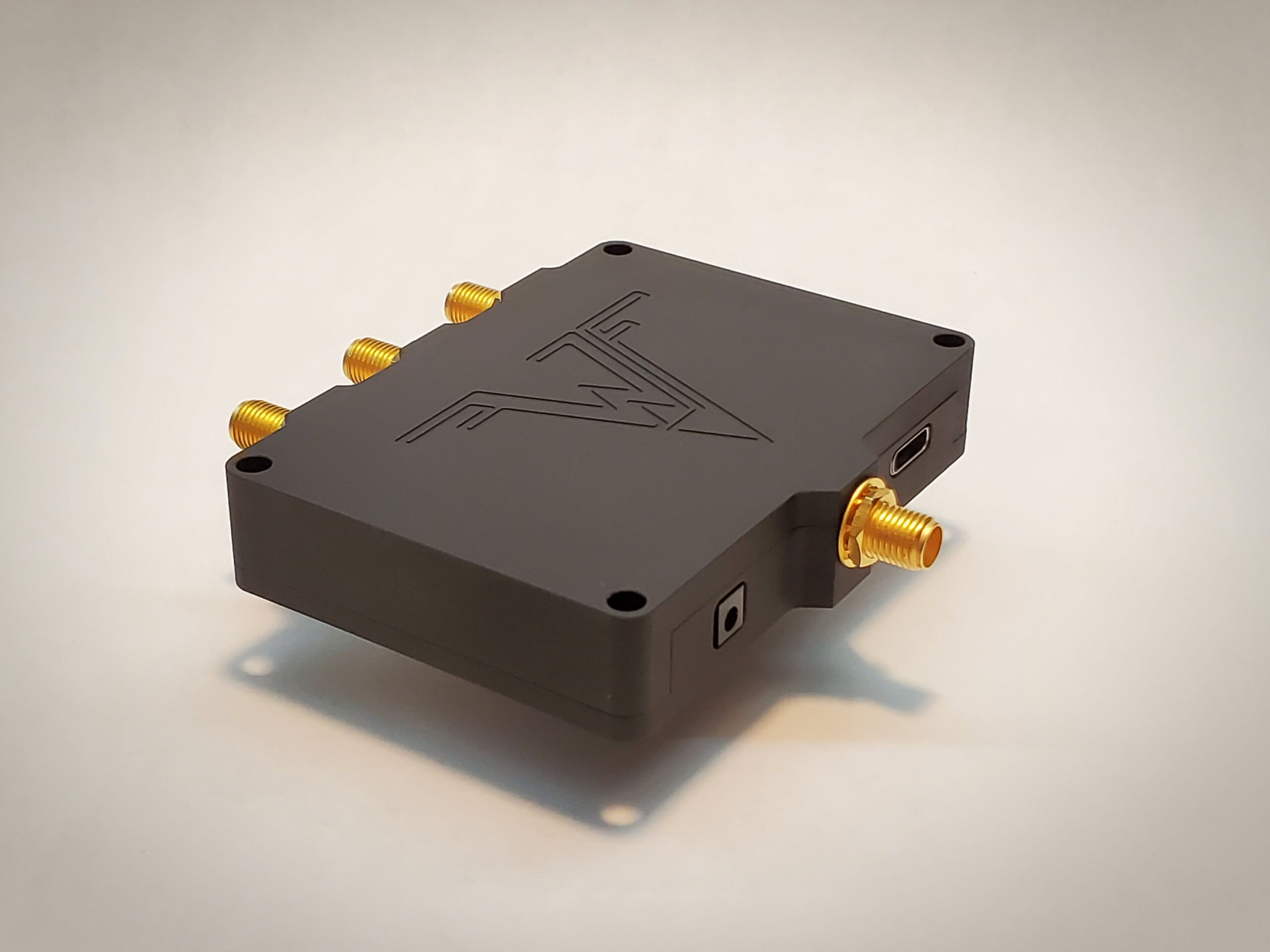
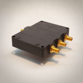
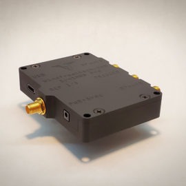
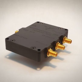
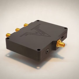
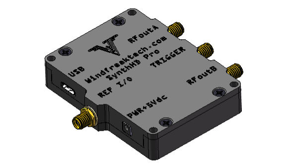
Milled aluminum case for better electrical performance and use in more rugged environments
SynthHD PRO has 100uS frequency step time
CE certification
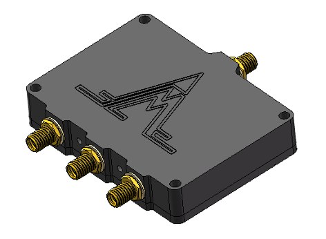
Easy stack-ability
Internal Operating Temperature: -40C to +85C (-40F to +185F)
The SynthHD PRO’s dual independent channels can be configured to run as two different frequencies, or the same frequency with different phases. This allows its use in antenna beam steering applications or quadrature signal generation commonly used in image reject frequency conversion.
The SynthHD PRO also has nonvolatile onboard flash memory so it can be programmed to fire up by itself on any frequency, power, sweep or modulation setting (and combinations thereof) to run without a PC in the field. This makes for a highly mobile, low power, and lightweight solution for your RF signal generation needs.
Expect excellent performance and high reliability despite the SynthHD Pro’s low cost.
In Stock. Ships within 5 business days.
We've Got You Covered:
No Hassle Refunds - 90 Day Money Back Guarantee!
Secure checkout via Credit Card, PayPal, and Venmo
The Windfreak SynthHD PRO RF signal generator is similar to the SynthHD but has these extra features:
Improved calibration for higher amplitude accuracy
Milled aluminum case for better electrical performance and use in more rugged environments
SynthHD PRO has 100uS frequency step time
CE certification
Easy stack-ability
Product Highlights:
10 MHZ to 24 GHZ in 0.1 Hz steps
-40 dBm to +18 dBm (typical) in 0.01 dB steps
Set each channel to independent frequencies and amplitudes
0 to 360 degrees coherent phase control in 0.01 degree steps on each channel
Stack multiple devices for coherent phase control on every channel
Select internal 10 or 27MHz reference or use external 10-100MHz reference
Pulse, AM, and FM internal modulation including FMCW radar chirp
Pulse Modulation with 1uS minimum width and 1uS resolution
Pulse, AM, and FM external modulation from DC – 10KHz
Powerful Trigger modes allow external triggering of most functions without a PC connected
Linear and list mode (frequency and amplitude hopping) sweeps include dual channel differential sweeps
Save all settings to the device for use without a PC
32 bit ARM processor onboard which is Arduino compatible
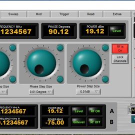
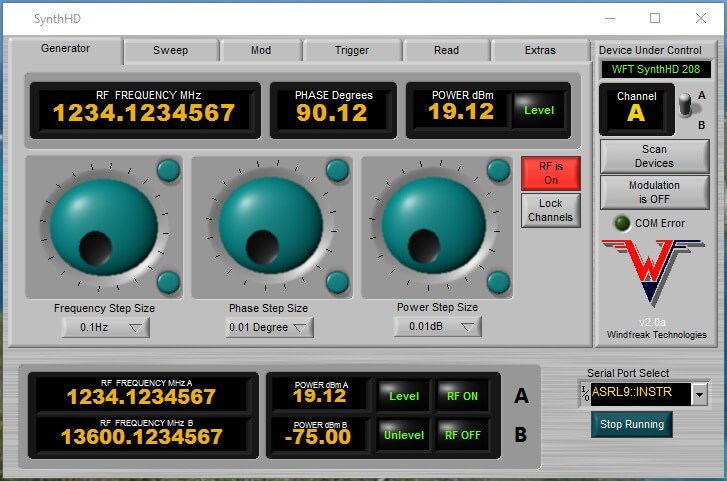
Complete Labview GUI executable and source code (pictured below) included with purchase
Windows, Linux, and Android compatibility
Designed and manufactured in the USA with maximized value and cost ratio
Contact us for custom firmware and hardware options
SynthHD Pro Software GUI (Labview source code included with purchase)
The following video shows the SynthHD Pro doing a Pulsed FM Radar Chirp (FMCW) that is simultaneously AM modulated.
The video below is taken with both channels driven into a mixer. The mixer is then fed into an oscilloscope and displayed on the right side of the video. The signal shows the DC and near DC downconverted component. The DC level depends on the phase relationship between the two channels. The switch on the far right of the GUI toggles between controlling channels (RFA or RFB).
For orders over 10 units discounts will apply. Request a quote here. Emails will be answered within 24 hours. Keep an eye on your SPAM folder. You will be given a lead time and a quote if you desire large volume.
Two channel frequency, phase and amplitude control
Quadrature (or other phase) LO signal generation
1Hz frequency resolution
01 degree phase control on each channel
100uS RF lock time standard
Up to +20dBm output power
01dB amplitude resolution
Over 50dB of power control
Absolute power display on Software GUI
10MHz – 100MHz external reference input
Selectable 10 or 27 MHz internal reference output
5ppm internal reference accuracy
Internal and external FM, AM, Pulse Modulation
Pulsed FMCW Chirp
External sweep, step and modulation trigger
500 point frequency and amplitude hop table
Dual channel frequency and amplitude lock
Channel enable / disable saves energy
5 Ultra low noise linear regulators on board
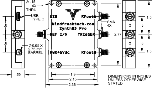
0 X 2.15 inches not including RF connectors
USB or UART control via USB-C connector
Operation from 20GHz to 24GHz is uncalibrated
Color: Black
Customer Benefits:
Run Complex Tests Faster and Reduce Equipment Cost: With two independent channels, you can perform stimulus/response tests, generate I/Q signals, or test antenna diversity with a single, affordable device, saving you the cost and complexity of a second generator.
Maximize Application Versatility with One Device: The 24GHz frequency range means you can go from testing simple radio circuits to developing advanced microwave applications without ever needing to switch signal generators. This one device can support nearly every project on your bench.
Simplify Your Test Setup: The wide, adjustable power range allows you to test highly sensitive receivers or drive amplifiers directly, often eliminating the need for external attenuators or extra amplification and reducing setup complexity.
Get to Work Immediately, Right Out of the Box: The included intuitive software and robust Labveiw GUI examples mean you can stop building custom control software and start running critical tests within minutes of opening the box.
Free Up Valuable Bench Space and Go Portable: Designed to be incredibly compact, the SynthHD PRO gives you back precious space on a crowded workbench. Its small size and low power consumption make it perfect for field testing, demos, or easy transport between labs.
Achieve Ultimate Operational Flexibility: Control the device from a PC for complex, automated test sequences, or use it in stand-alone mode with included power supply for simple, repetitive tasks without tying up a computer. This flexibility adapts to your workflow.
Accurately Emulate Real-World Scenarios: Go beyond simple CW tones. The built-in AM, FM, and Pulse modulation capabilities allow you to create dynamic signals that more accurately represent the conditions your device will face in the real world.
Specifications
SynthHD PRO v2 Hardware Improvements:
Frequency response improved to 10MHz to 24GHz
Amplitude calibration from 10MHz to 20GHz
No 1/2 subharmonic on frequencies below 15GHz
Better high-frequency RF power around +15dBm at 10GHz and +8dBm at 20GHz
Better high-frequency RF pulse on/off isolation and speed
500 point nonvolatile frequency and amplitude hop table
Better no-compensation amplitude stability over temperature
USB-C connector is tougher, plus brings in native UART control
Switch to 5V power supply
Larger faster flash memory for larger calibration, step, and modulation tables
New software is backwards compatible to version 1 devices
1. USB and UART Warning
The SynthHD Pro v2 was designed to work with, and ships with, a USB 2 cable. Use a USB 3 cable only when tapping into the UART signals for 3.3V COM port control of the SynthHD Pro with your own microcontroller circuit. Using a USB 3 cable attached to a USB 3 port on a PC may have unknown consequences as the PC is not designed to see the SynthHD UART signals and vv. See UART app note for UART usage instructions.
2. Characteristics
2.1 Electrical Characteristics
Characteristic
Min.
Typ.
Max.
Unit
Notes
Supply Voltage
4.7
5
5.5
V
Suggested 2A minimum
Supply Current
900
1200
mA
420mA per channel
Standby Supply Current
70
mA
Both RF channels OFF
RF Output Frequency Range
10
-
24000
MHz
Calibrated Frequency Range
10
20000
MHz
RF Output Power Maximum
6
17
20
dBm
See graph
RF Output Power Minimum
-40
dBm
See graph
RF OFF Output Power
-90
dBm
100% shutdown of RF section
RF Frequency Resolution
0.1
Hz
Default is 100Hz selectable by Channel Spacing Setting
RF Output Power Resolution
0.01
dB
RF Phase Resolution
0.01
°
** See note 1
RF Output Impedance
50
Ω
Internal Reference Frequency
10 or 27
MHz
Selectable
Internal Reference Tolerance
2.5
ppm
External Reference Frequency
10
-
100
MHz
Keep phase comparator less than 100MHz
External Reference Level
10
dBm
Keep below 3.3Vpp
Trigger
-0.3
3.3
V
Internally pulled up
UART
-0.3
3.3
V
Note 1: Phase tuning speed, phase resolution, and carrier frequency are inter-related. Phase tuning speed slows as RF carrier frequency and Channel Spacing settings decrease. Smaller Channel Spacing will have higher phase and frequency resolutions but slower phase tuning speed. Going below 100MHz carrier with smaller Channel Spacing than 100Hz may be prohibitively slow and/or erratic.
2.2 Thermal Operating Characteristics
Description
Min
Max
Unit
Notes
Operating Temperature
-40
30
°C
Without airflow or heatsinking
Operating Temperature
-40
75 Internal
°C
Query internal temperature sensor with software and keep below 75C with airflow, heat sinking or limited duty cycle.
3. Typical Performance
3.1 RF Output Power
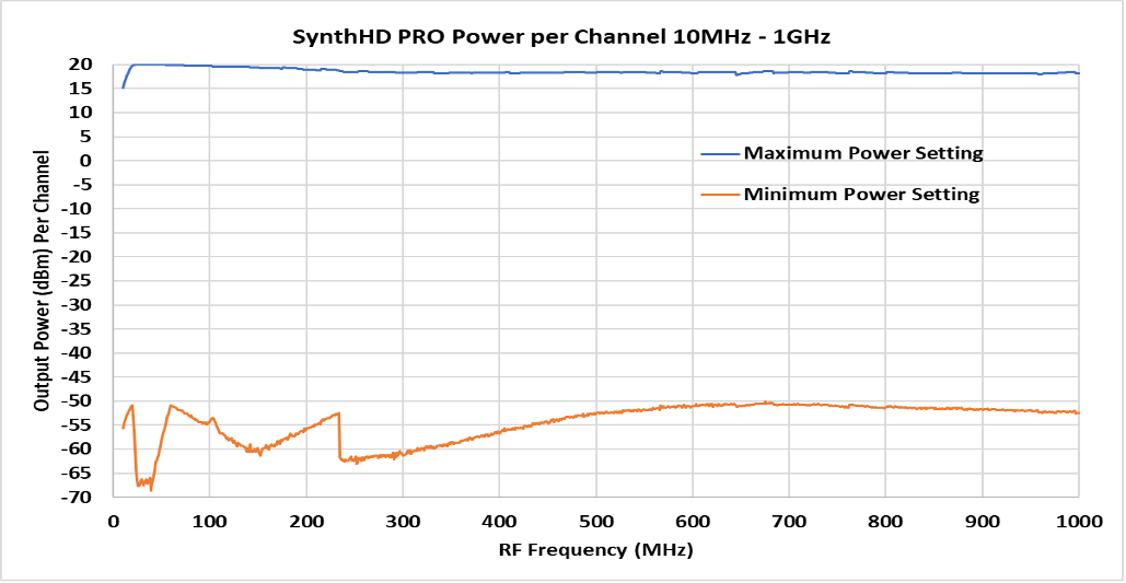
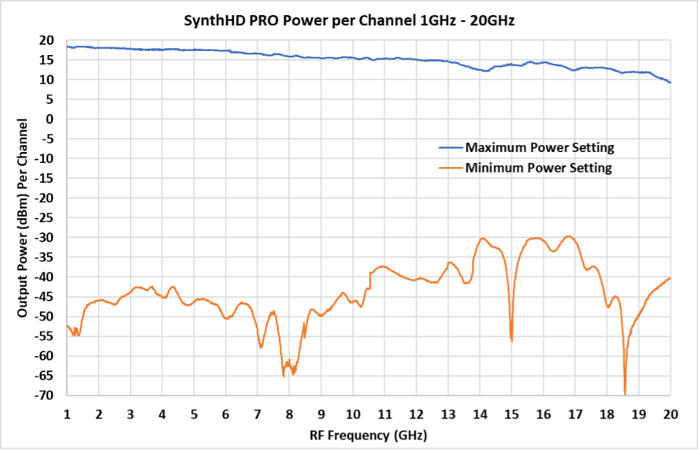
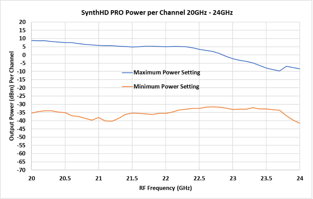
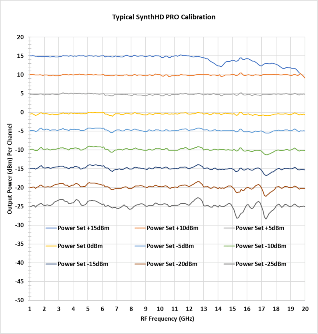
The typical output power (per channel) of the SynthHD PRO is shown below. This graph is of raw unleveled operation at both the maximum and minimum gain settings of the output variable gain section. Gain is set via dBm power commands allowing output power levels anywhere in the range between the minimum and maximum levels shown below. RF port power and frequency can be set independent of each other. Power levels are settable in 0.01dBm increments. On board calibration is attained through a look up table for each channel. Device calibration is performed at the factory and stored in onboard flash memory. Calibration is good from 10MHz to 20GHz. Operation from 20GHz to 24GHz is uncalibrated and unspecified. All parts of the signal chain have high quality voltage regulation, and the D/A’s driving the VGAs have a 1% voltage reference controlling their outputs.
Note: +15dBm setting hitting max power limit above 12GHz
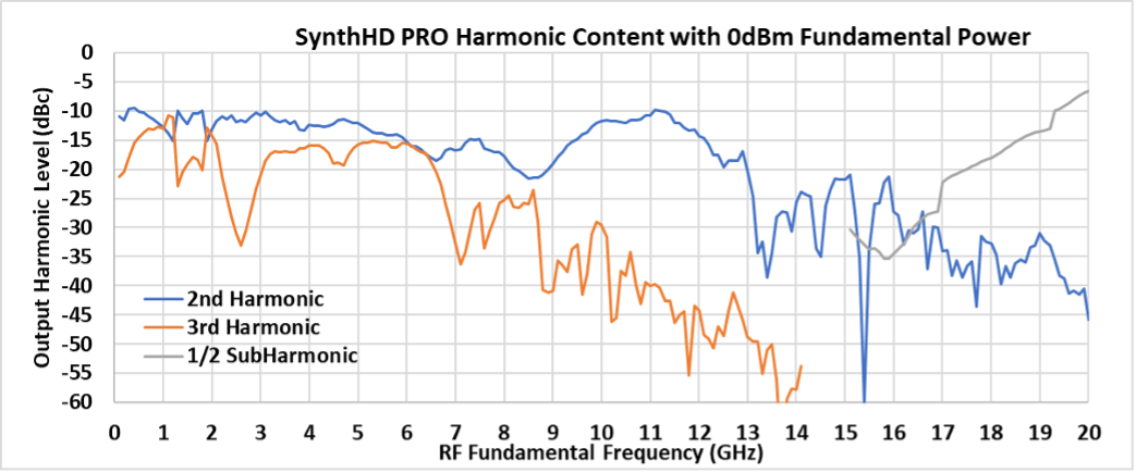
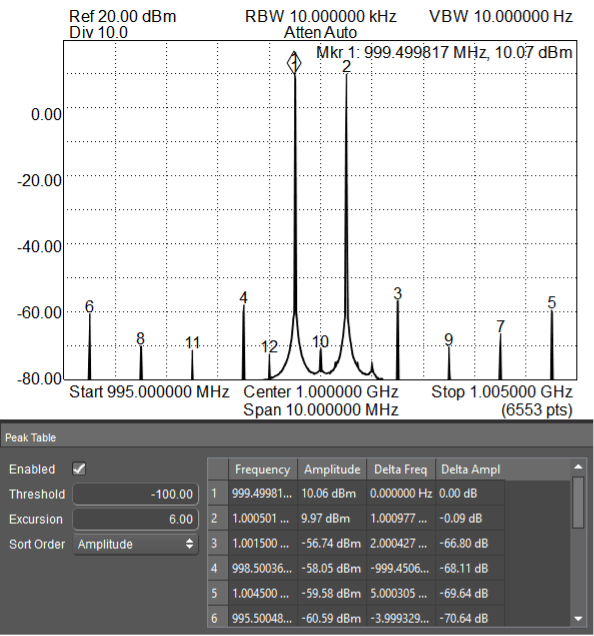
3.2 RF Output Harmonic Content
The typical SynthHD PRO harmonic distortion is shown below for the second and third harmonics. Also shown is a subharmonic created when generating fundamental frequencies above 15GHz. All frequencies above 15GHz are generated with an RF doubler. This data is taken at a leveled fundamental power of 0dBm.
If lower harmonic and subharmonic levels are needed, Windfreak Technologies suggest the use of low cost SMA filters from Crystek and Minicircuits.
Example: Crystek Lowpass Filter – many cutoff frequencies, 1GHz example: CLPFL-1000, $25
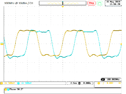
Typical 100MHz waveform, both channels adjusted to 90 degrees offset (500MHz scope).
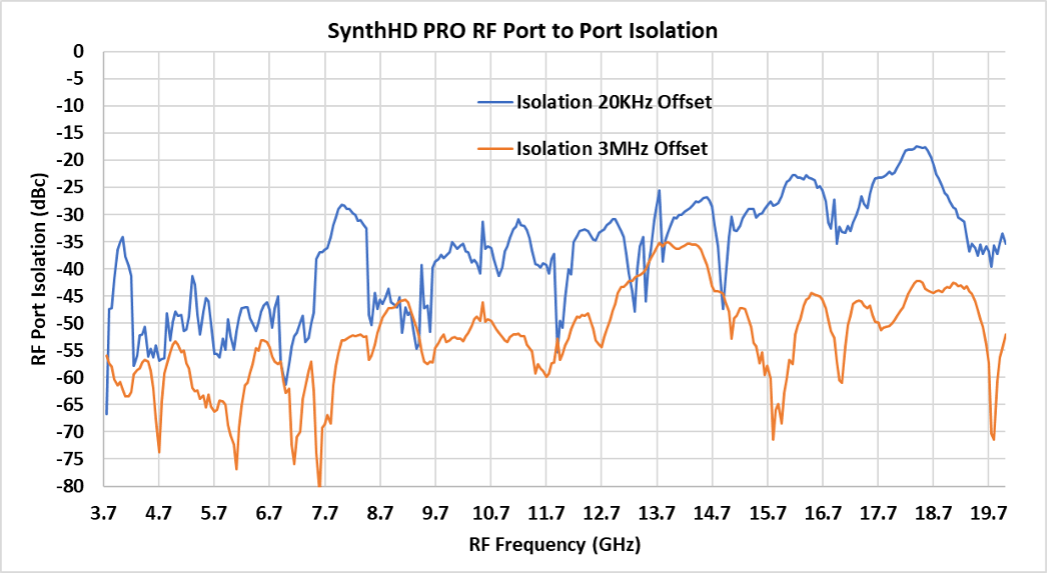
3.3 RF Port to Port Isolation
Port to port isolation is shown below with both channels at 0dBm output power. One trace is taken with a 3MHz offset between channels. The other trace is taken with a 20KHz offset between channels. The 20KHz offset places each signal within each other’s loop bandwidth and the leakage modulates each other’s VCO control voltages where loop gain is high. Offsets inside the loop bandwidth will have worse isolation. The below data is taken with both PLL_ICP settings at 15.
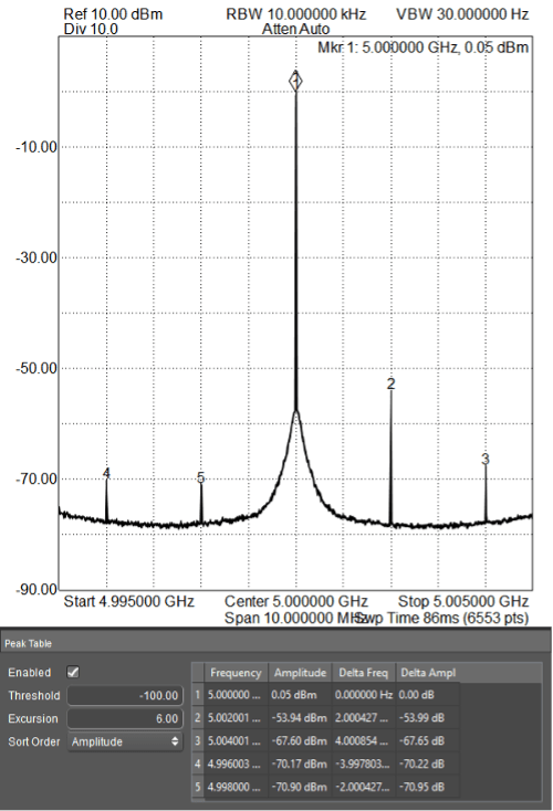
Note: Performance below 3.7 GHz continues to trend downward.5GHz Port to Port Isolation Spectrum with +1MHz Offset
Note: The plot above shows the conducted port at 5.0 GHz. The terminated port is set at 5.001 GHz. The spur location is at a 2MHz offset since the SynthHD Pro uses an RF divide by 2 circuit to achieve 5GHz. As the RF frequency decreases, the isolation spurs move out, until they are eventually outside of the loop bandwidth and thus significantly attenuated.
3.4 Integer Boundary Spurs
A mechanism for in band fractional spur creation in all fractional PLL’s is the interactions between the RF VCO frequency and the internal 27MHz, internal 10MHz or arbitrary external reference frequency. When these frequencies are not integer related, spur sidebands appear on the VCO output spectrum at an offset frequency that corresponds to the difference in frequency between an integer multiple of the reference and the VCO frequency. These spurs are attenuated when outside the loop filter which is 12KHz wide. By having two selectable internal reference frequencies of 10MHz and 27MHz the problem is eliminated by switching reference frequencies when working around a boundary.
Example if using the SynthHD PRO 27MHz internal reference: For the fundamental VCO range of 3400MHz to 6800MHz the first integer boundary happens at 27MHz X 126 = 3402MHz, the next at 27MHz X 127 = 3429MHz and every 27MHz thereafter up to 6777MHz. Above and below the fundamental VCO band the spacing will be affected by the RF doubler or RF divider respectively. If the desired VCO operating frequency is 3402.01MHz this would give spurs 10KHz on either side of the carrier that may be unacceptable. In this case, using the 10MHz reference would be suggested since its closest integer boundary is at 3400MHz. Spurs 2MHz away will be attenuated to satisfactory levels by the loop filter.
3.6 Intermodulation Distortion after an External Wilkinson Combiner
It’s possible to lock both channels in both frequency and amplitude for easy tuning during IMD testing of IP3 in passive and active components. The plot below shows two tones combined with a YL-70 0.5-2.0 GHz KL combiner that has roughly 20dB of isolation between ports. The tones are centered at 1GHz and separated by 1MHz. This method will allow for IP3 testing below roughly +40dBm.
Two Tone Generation Via Wilkinson Combiner
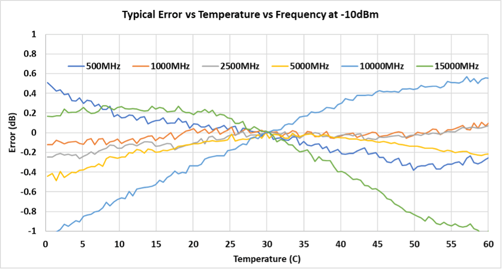
3.7 Performance over Temperature
The SynthHD Pro has an algorithm to reduce amplitude drift over temperature. The user can specify 4 different control settings in the firmware.
No temperature compensation
Compensation only during a frequency or amplitude setting
#1 plus periodic adjustments every 1 second
#1 plus periodic adjustments every 10 seconds (factory default)
Temperature compensation 2 and 3 are turned off during active modulation. Frequency sweeps and hops are only compensated for each step unless the setting is 0.
All subsequent temperature plots are based on an internal temperature measurement with temperature compensation turned ON. When the SynthHD has one RF channel turned on in a lab environment with moderate airflow at 25°C the internal temperature will usually be around 40°C.